

Wireless Communication
 EU RED Network Security Standard EN 18031
 Wireless and communication detection
 Mobile communication product certification
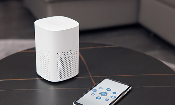 Bluetooth BQB Product Certification
 FM/AM Product Certification
 WiFi Product Certification
 Wireless charging product certification
 Interphone product certification
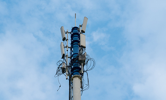 Base station certification
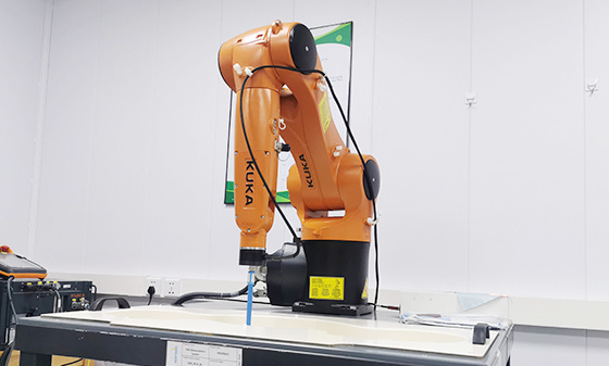 SAR testing
 Receiver Product Certification
 5G NR Product Certification
 UWB Product Certification
 Internet of Things authentication
Electromagnetic compatibility
 Automotive Electronics EMC Testing
 EMC rectification
 EMC
EMC
Automotive Electronics
 Electrical performance testing
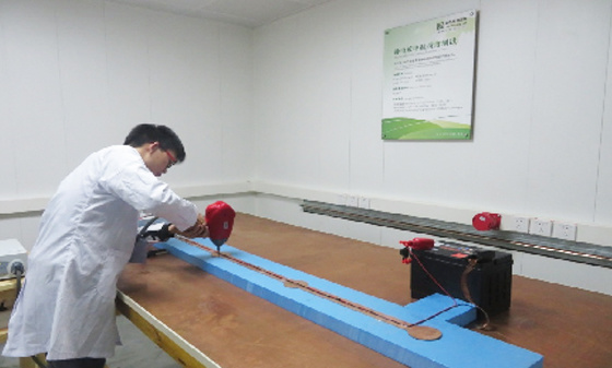 EMS testing - radiation anti-interference testing system (including radar waves)
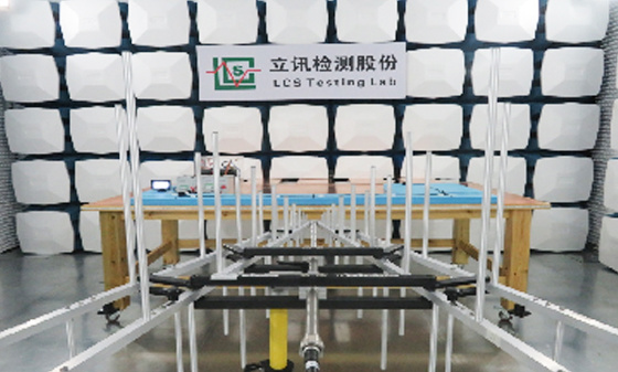 EMS Testing - Electrostatic Discharge
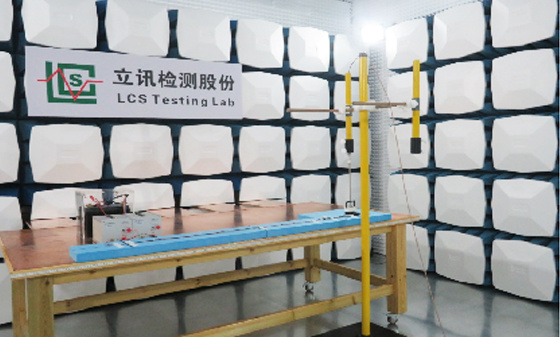 EMS Test - Transient Conducted Immunity Test
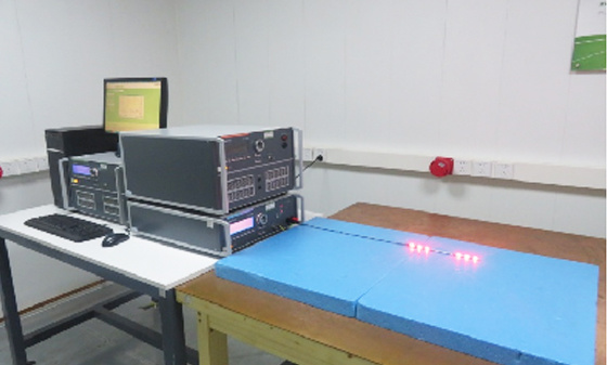 EMS Testing - Portable Transmitter Immunity
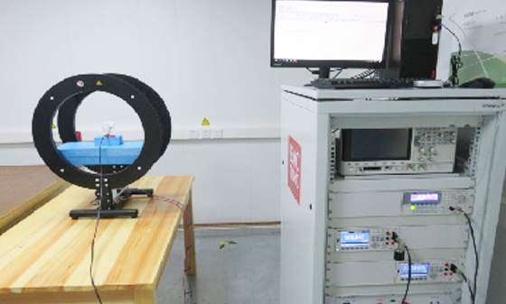 EMS Test - High Current Injection (BCI) Test
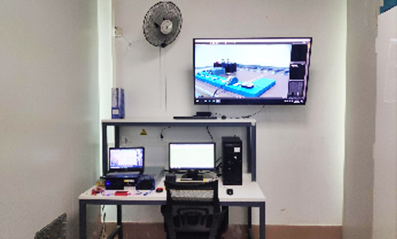 EMS test - low-frequency magnetic field anti-interference test
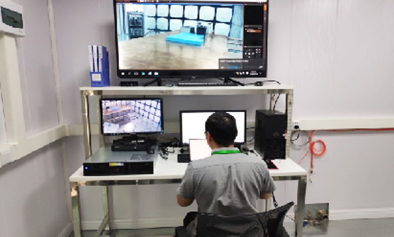 EMI Testing - Transient Conducted Emissions Testing System
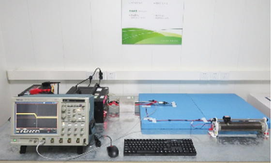 EMI testing - low-frequency magnetic field emission
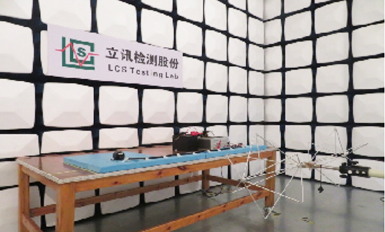 EMI Test - Radiation Emission Test
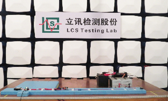 EMI Test - Conducted Emissions Test
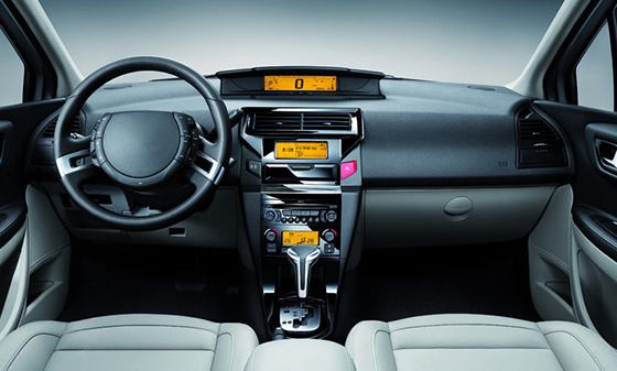 Automotive Electronic Testing
Automotive Parts Inspection
 Automotive ELV&VOC
 Reliability testing
 Temperature shock test
 Vibration testing
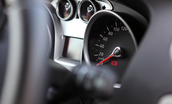 Instrument panel/instrument panel three comprehensive vibration test
 Comprehensive vibration test of door inner panel III
 Sunvisor Three Comprehensive Vibration Test
 Spoiler Three Comprehensive Vibration Test
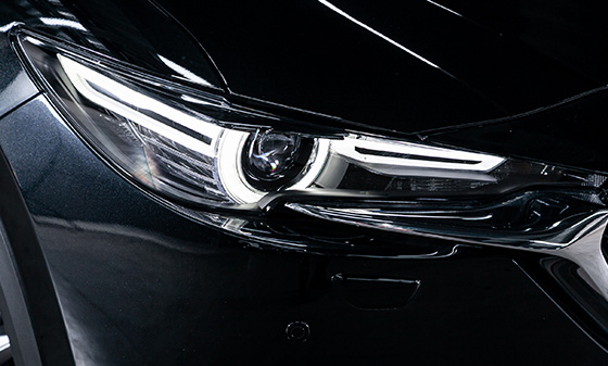 Three comprehensive vibration tests of car front and rear bumpers
 Three comprehensive vibration tests for lamp housing/lampshade
 Comprehensive vibration test of outer circumference three
 Automotive metal material testing
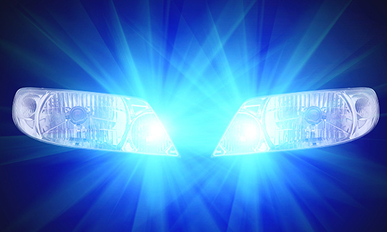 Performance testing of automotive lighting fixtures
 Rapid temperature change test
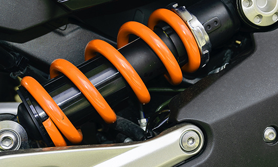 Vibration
 Common issues with vibration testing
 Common issues with fatigue testing
 Common issues with high and low temperature testing
 Conducted Interference (CE) - Suzhou Lixun Standard
 Electromagnetic Radiation Tolerance Test (RS) - Suzhou LCS Standard
 Electrical Fast Pulse Withstand Test (EFT) - Suzhou LCS Standard
 Voltage flicker test - Suzhou LCS standard
Electronic appliances
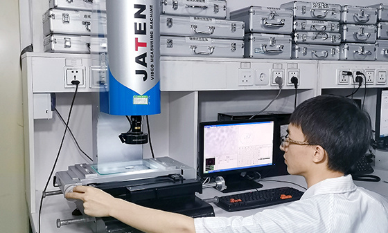 Household appliance product testing
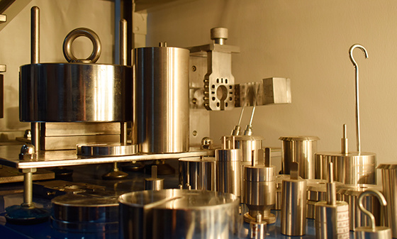 Electrical accessory product testing
 Household appliance testing
Chemical Testing
 Introduction to PFAS Testing
 MOSH/MOAH Mineral Oil Testing Service
 MOSH/MOAH Mineral Oil Testing and Certification Report Service
 Consumer Product Testing Services - WEEE Chapter
 Ecological textile testing
 Leather Footwear Inspection
 Food contact material testing
 Testing of toys and baby products
 Hazardous substance testing
Electronic Cigarette Testing
 Electronic cigarette detection
Reliability testing
 Other tests - pencil hardness test
 Mechanical testing - Packaging compression test
 Climate environment testing - Xenon lamp aging test
Battery Testing
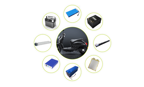 Power storage battery testing and certification
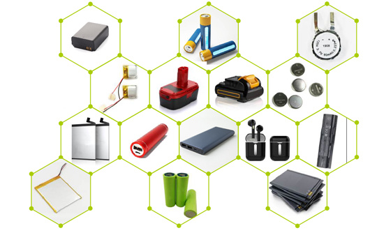 Consumer Electronics Battery Testing and Certification
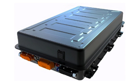 power battery
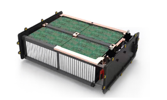 Light electric vehicle batteries
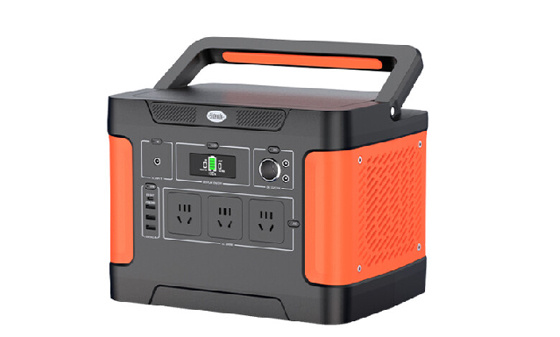 Energy storage battery
 Portable battery
 Battery testing
 battery test
Lamp Inspection
 Inspection of ship lighting fixtures
 COI Index Test for Medical Indoor Lighting
 Lamp safety inspection
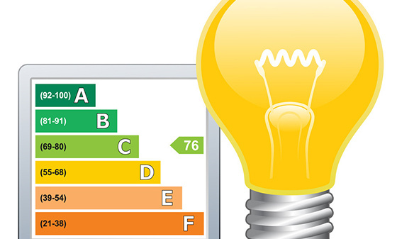 Luminaire energy efficiency testing
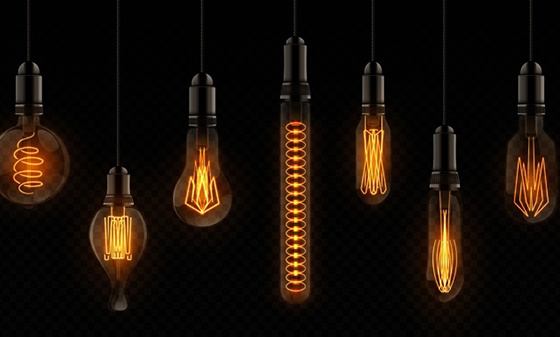 EMC testing of lighting fixtures
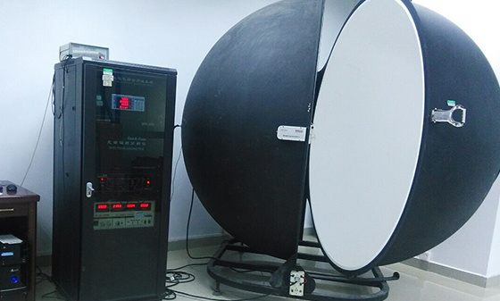 Integral Ball Laboratory
 Photobiology Experiment
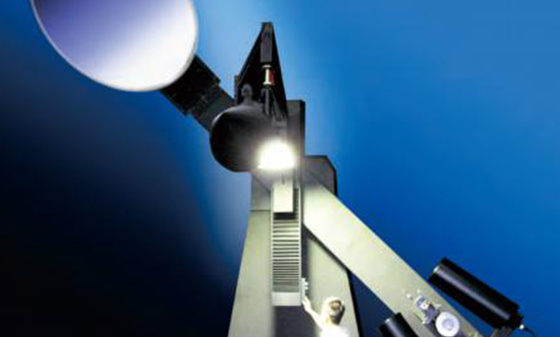 Light distribution test
 Lamp aging test
 Lamp IP waterproof
 Lamp performance testing
 Lamp reliability testing
Children's toy testing
 Testing standards for toy products
China Certification
 China's "national promotion" RoHS certification
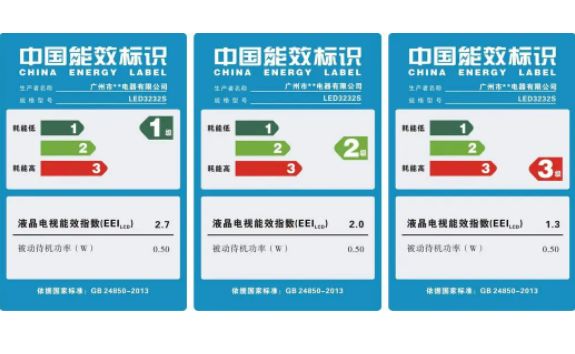 China Energy Efficiency Label Certification
 China Energy Conservation Certification
 China CQC Certification
 Tmall JD Quality Inspection Report
 China SRRC Certification
 Taiwan BSMI certification
 Taiwan NCC certification
 China CCC Compulsory Certification
Asia Certification
 Vietnam certification
 KC certification
 KUCAS Certification in Kuwait
 Singapore PSB certification
 Iraq COC Certification
 IMDA certification
 VCCI Certification in Japan
 JATE certification in Japan
 PSE certification
 BIS certification
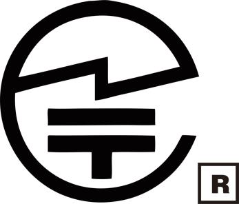 Japanese TELEC certification
European Certification
 RoHS certification
 GOST certification in Russia
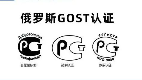 Russian EAC certification
 Northern Ireland UKNI logo
 Electrical ENEC certification
 European D-MARK certification
 Türkiye BTK certification
 TSE certification in Türkiye
 CE certification in Türkiye
 RED certification
 German TUV-SUD certification
 CE-ERP certification
 REACH certification
 German GS certification
 EU E-Mark certification
North American Certification
 Ecuador VOC certification
 Mexico NOM certification
 IRAM certification
 CPSC Certification in the United States
 CSA certification
 ASTM certification
 FDA certification
 CEC certification
 ETL certification
 ul certification
 IC certification
 Energy Star
 FCC Certification in the United States
 ASTM certification
Middle East Certification
 Israel SII certification
 Saudi SABER certification
 GCC certification for the seven Gulf countries
 Iran COI certification
 Qatar COC Certification
 Iraq COC Certification
 Saudi EER Energy Efficiency Certification
 Saudi SABER certification
 Algeria PCA certification
 PVOC certification
Australia Certification
 New Zealand IC-F testing
 VEET certification
 LCP certification
 GEMS certification
 RCM certification
 C-Tick certification
 SAA certification
Africa Certification
 Gabon COC certification
 Algeria COC certification

 Ethiopian VOC and COC certification
 Mauritius VOC certification
 Ghana COC certification
 COC certification in Burundi
 Zambia COC certification
 Botswana COC Certification
 Uganda PVOC certification
 SABS certification in South Africa
 South African LOA certification
 Zimbabwe CBCA Certification
 Nigeria SONCAP certification
 Kenya PVOC certification
 African COC certification
Other certifications
 WEEE
WEEE
 Bluetooth BQB certification
 IECEE registration
 MHRA registration in the UK
TRAINING
 Management system training
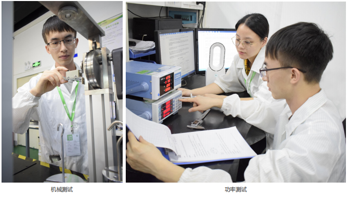 Laboratory technical training
 Laboratory Process Consulting
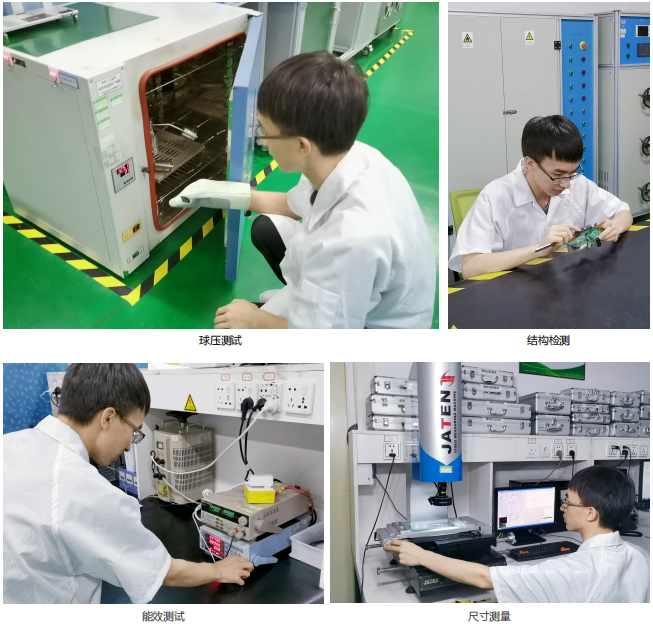 Laboratory decoration construction
Wireless Communication
Electromagnetic compatibility
Automotive Electronics
Automotive Parts Inspection
Electronic appliances
Chemical Testing
Electronic Cigarette Testing
Reliability testing
Battery Testing
Lamp Inspection
Children's toy testing
China Certification
Asia Certification
European Certification
North American Certification
Middle East Certification
Australia Certification
Africa Certification
Other certifications
TRAINING
Wireless Communication
Electromagnetic compatibility
Automotive Electronics
Automotive Parts Inspection
Electronic appliances
Chemical Testing
Electronic Cigarette Testing
Reliability testing
Battery Testing
Lamp Inspection
Children's toy testing
China Certification
Asia Certification
European Certification
North American Certification
Middle East Certification
Australia Certification
Africa Certification
Other certifications
TRAINING
Wireless Communication
Electromagnetic compatibility
Automotive Electronics
Automotive Parts Inspection
Electronic appliances
Chemical Testing
Electronic Cigarette Testing
Reliability testing
Battery Testing
Lamp Inspection
Children's toy testing
China Certification
Asia Certification
European Certification
North American Certification
Middle East Certification
Australia Certification
Africa Certification
Other certifications
TRAINING
Wireless Communication
Electromagnetic compatibility
Automotive Electronics
Automotive Parts Inspection
Electronic appliances
Chemical Testing
Electronic Cigarette Testing
Reliability testing
Battery Testing
Lamp Inspection
Children's toy testing
China Certification
Asia Certification
European Certification
North American Certification
Middle East Certification
Australia Certification
Africa Certification
Other certifications
TRAINING
Wireless Communication
Electromagnetic compatibility
Automotive Electronics
Automotive Parts Inspection
Electronic appliances
Chemical Testing
Electronic Cigarette Testing
Reliability testing
Battery Testing
Lamp Inspection
Children's toy testing
China Certification
Asia Certification
European Certification
North American Certification
Middle East Certification
Australia Certification
Africa Certification
Other certifications
TRAINING
Wireless Communication
Electromagnetic compatibility
Automotive Electronics
Automotive Parts Inspection
Electronic appliances
Chemical Testing
Electronic Cigarette Testing
Reliability testing
Battery Testing
Lamp Inspection
Children's toy testing
China Certification
Asia Certification
European Certification
North American Certification
Middle East Certification
Australia Certification
Africa Certification
Other certifications
TRAINING

EMC Antenna Selection Pitfalls Guide: Comprehensive Core Parameters + Frequency Band Matching Logic
Author.
LCS
Source:
Post time:
2026-07-13
In the electromagnetic compatibility (EMC) testing system, the antenna serves as the core component for both radiation emission measurement and immunity testing. It is responsible for capturing unintentional radiation signals from the equipment under test (EUT) and generating interference fields of specified intensity according to standard requirements. Antenna performance directly determines testing accuracy, frequency band coverage, and result reproducibility. A misselection can lead to data distortion requiring retesting in mild cases, or result in invalidated batch reports and questioned laboratory qualifications in severe cases.
This article systematically breaks down the professional key points of EMC testing antennas, covering the principles of antenna transmission and reception, six core parameters, frequency band selection logic, and the differences between near-field and far-field scenarios.
1. Mutual Exchange with Distinct Focus: Fundamental Positioning of EMC Antennas
In EMC testing, the antenna serves two primary functions:
Receiving Mode – Precisely measure the radiation emissions of the EUT and capture weak electromagnetic interference signals. In this mode, the antenna emphasizes sensitivity and low-noise characteristics, ensuring effective detection even when the EUT's radiation is significantly below the standard limits.
Emission Mode – Generate a standard electromagnetic field for radiation sensitivity (RS) testing to verify the device's immunity to interference. In this mode, the antenna focuses more on field strength uniformity and power handling capacity, ensuring the field strength distribution in the EUT's area meets standards and the antenna itself remains undamaged.
From a physical perspective, all antennas exhibit reciprocity between transmission and reception. However, in practical engineering, the optimization directions of receiving and transmitting antennas differ—the former aims for "clear reception," while the latter focuses on "accurate transmission." When selecting antenna types, it is essential to clearly define their primary purpose and avoid indiscriminate interchange.

Bandwidth expansion rules:
Non resonant antenna bandwidth>resonant antenna
Low gain antenna bandwidth>high gain antenna
Broadband matching network can significantly expand bandwidth, with priority higher than antenna coefficient optimization
Practical conclusion: Multi antenna combination is a routine solution in EMC laboratory. A single full frequency band test usually requires 3-5 antennas to cooperate and cover, with each antenna responsible for a specific frequency band interval.
⑤ Impedance and Standing Wave Ratio (VSWR)
Impedance: The standard impedance for EMC testing systems is 50 Ω. The antenna needs to be well matched with a 50 Ω system within the operating frequency band. The low-frequency magnetic field loop antenna is a difficult frequency band for impedance matching due to the significant drift of equivalent impedance with frequency.
Standing Wave Ratio (VSWR): An indicator that measures the degree of impedance matching between an antenna and a transmission line. The larger the VSWR, the more severe the signal reflection, the greater the actual radiated or received power loss, and the measurement error is also amplified accordingly.
Application points: In precision measurement and high-frequency high-power radiation sensitivity testing, VSWR must be strictly controlled. The general requirement is that the VSWR within the operating frequency band should be ≤ 2.0:1, and the critical frequency points should be controlled within 1.5:1.
⑥ Size
The physical size is the core constraint of EMC antennas, which directly affects test results and deployment flexibility:
Advantages of small antenna: reduces parasitic coupling with shielding room walls, ground planes, and EUTs, facilitating mobile deployment and near-field measurement positioning
Advantages of a large antenna: better low-frequency response, higher gain, and wider bandwidth
Compromise principle: Prioritize the selection of small-sized antennas while meeting the requirements for gain and bandwidth. Especially in standard 3-meter or 10 meter semi anechoic chambers, excessive antenna size will significantly affect the attenuation characteristics of the site.
3、 Matching by frequency band: Four segment antenna selection scheme
The EMC testing frequency range is large, and dedicated antennas must be matched according to the frequency range to balance performance and practicality
Below 100MHz (low frequency band)
Electric field measurement: Rod antenna (non resonant type, negative gain, compact size, suitable for low-frequency electric field scanning)
Magnetic Field Measurement: Shielded Loop Antenna (Specialized H-Field Test, Essential Device for Near Field Magnetic Field Measurement)
Selection logic: Low frequency band, long wavelength, unrealistic physical size of resonant antenna, non resonant antenna is the optimal solution
100MHz~200MHz (mid low frequency band)
Preferred broadband resonant antenna, balancing bandwidth coverage and gain level
In scenarios where installation space is limited, non resonant antennas can be used to exchange bandwidth for size
200MHz~1GHz (mid to high frequency band)
Core component: Logarithmic periodic antenna
Features: Broadband, high gain, wide coverage, strong versatility
Positioning: The main antenna of EMC laboratory, where the vast majority of radiation emission tests are completed in this frequency band
Above 1GHz (high frequency band)
Core component: Dual ridge waveguide horn antenna
Features: High gain, good uniformity of field strength
Applicable: Radiated disturbance and immunity testing at 1~2GHz and above
Industry standard configuration: A single full band test requires 3-5 antenna combinations to cover electric field, magnetic field, low frequency, medium frequency, and high frequency requirements.
4、 Near Field vs Far Field: Differences in Antenna Usage in Test Scenarios
▎ Far field (standard radiation emission test scenario)
Electromagnetic waves propagate in the form of plane waves
The E-field and H-field satisfy a fixed proportional relationship of 377 Ω free space wave impedance
Measure one of the parameters to convert to another
It is the mainstream scenario for standard certification testing (such as 3-meter method, 10 meter method)
Near field (fault diagnosis and interference source localization scenario)
The wave impedance is unknown, and there is no fixed ratio between the E-field and H-field
It is necessary to use dedicated E-field probes and H-field loop antennas separately for independent measurement
Commonly used for electromagnetic interference investigation, PCB radiation source positioning, and cable coupling analysis in the product development stage
Key difference: Far field testing focuses on "quantity" - whether the radiation emission exceeds the standard; Near field testing focuses on the "source" - where interference comes from. The antenna selection logic for the two scenarios is completely different and cannot be mixed.
5、 Five step process for selecting laboratory standards
Step 1: Clarify the testing requirements and determine the testing type (radiation emission RE/radiation sensitivity RS), applicable standard frequency range, minimum field strength or sensitivity requirements, and shielding room/darkroom size limitations.
Step 2: Match antenna parameters and check item by item: frequency coverage range, gain flatness, antenna coefficient calibration curve, VSWR working band, and whether physical dimensions are suitable for the testing site.
Step 3: Verify calibration qualifications. Antennas must have original factory calibration curves or certificates and support regular re inspection. The traceability of calibration data to national metrological standards is a prerequisite for the CMA/CNAS legal validity of testing reports.
Step 4: Evaluate the manufacturer and select a manufacturer with comprehensive technical support and convenient calibration and repair after sales. Antennas are precision measuring instruments, and reliability takes priority over price - a single calibration error may result in the failure of the entire batch of reports.
Step 5: Determine the combination scheme and split the antenna configuration by frequency band to avoid overloading and wideband operation of a single antenna. Clearly define the coverage area and switching frequency of each antenna to ensure the accuracy of full frequency band testing and data continuity.
EMC antenna is not a universal RF device, but a precision measuring tool for electromagnetic compatibility testing. From gain, antenna coefficient to VSWR, each parameter is directly mapped to the accuracy and legal validity of the test data. Selecting the right antenna, configuring the appropriate combination, and conducting regular calibration - this is the underlying logic of EMC laboratory data compliance.
If you need to obtain the LCS Lite On EMC laboratory antenna configuration list or radiation emission/sensitivity testing plan, please feel free to contact LCS for one-on-one technical consultation.
Related articles
New articles
Interpretation of LITE technology 9th issue
2026-09-28
Interpretation of LITE Technology 8th Issue
2026-09-24
Media Center
Latest News
Contact Us
National 24-hour service hotline
400-116-2629
Group Headquarters
E-mail: webmaster@lcs-cert.com
Address: Shenzhen City, Baoan District, Shajing Street, Nga side of the school of Wei Juji Industrial Park, Building A 1 ~ 2 floor, Building C 3 floor


 WeChat Inquiry


 Reservation


Contact Us
National 24-hour service hotline
Address:Juji Industrial Park, Xueziwei, Ngabian, Shajing Street, Baoan District, Shenzhen Building A 1~2F, Building C 3F

WeChat public number
Share industry dry goods

WeChat consultation
Please note consulting services

Follow Jitterbug

Mobile website
di complaint mailbox: customer.complaint@lcs-cert.com complaint telephone tel: 18126445450 certificate report verification of authenticity mailbox: verification@lcs-cert.com