

Wireless Communication
 EU RED Network Security Standard EN 18031
 Wireless and communication detection
 Mobile communication product certification
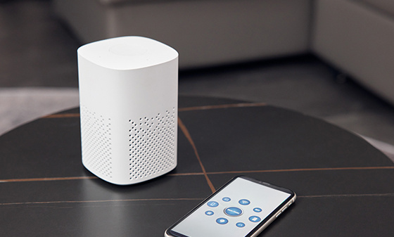 Bluetooth BQB Product Certification
 FM/AM Product Certification
 WiFi Product Certification
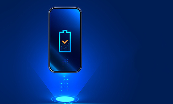 Wireless charging product certification
 Interphone product certification
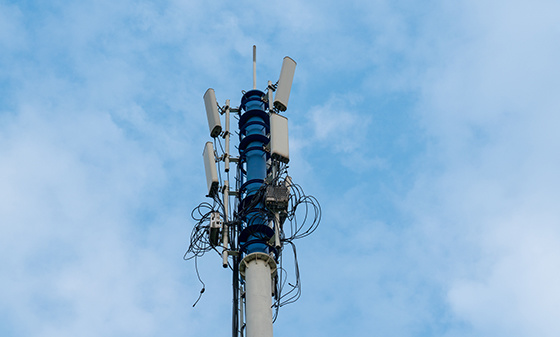 Base station certification
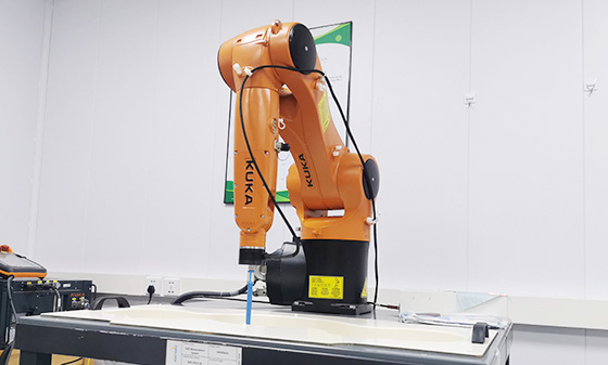 SAR testing
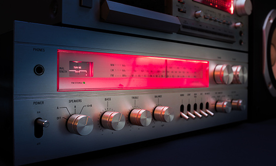 Receiver Product Certification
 5G NR Product Certification
 UWB Product Certification
 Internet of Things authentication
Electromagnetic compatibility
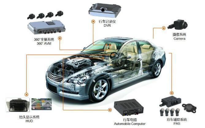 Automotive Electronics EMC Testing
 EMC rectification
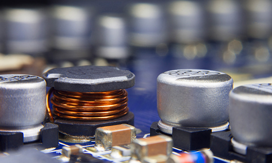 EMC
Automotive Electronics
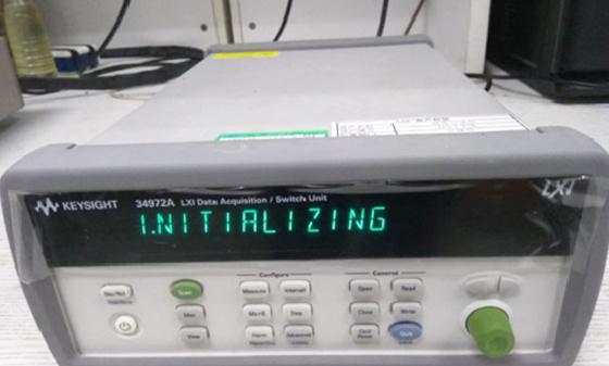 Electrical performance testing
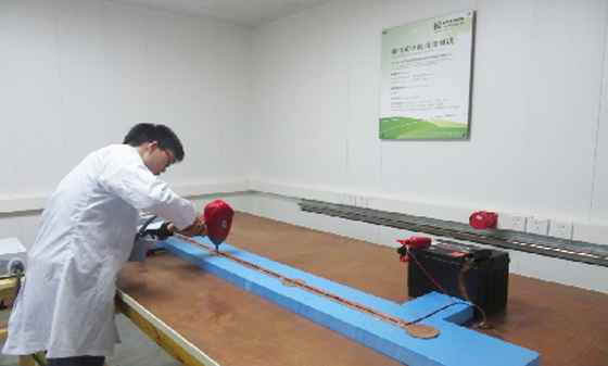 EMS testing - radiation anti-interference testing system (including radar waves)
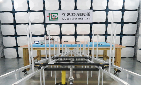 EMS Testing - Electrostatic Discharge
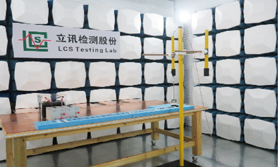 EMS Test - Transient Conducted Immunity Test
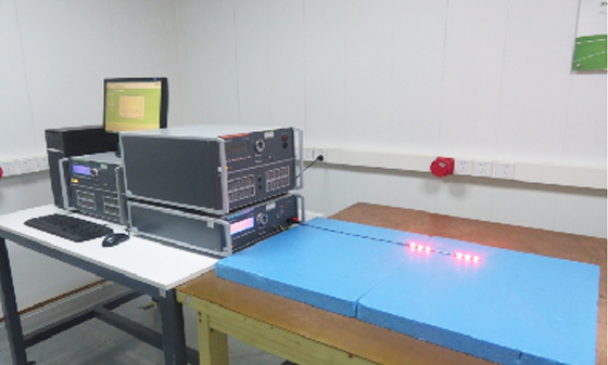 EMS Testing - Portable Transmitter Immunity
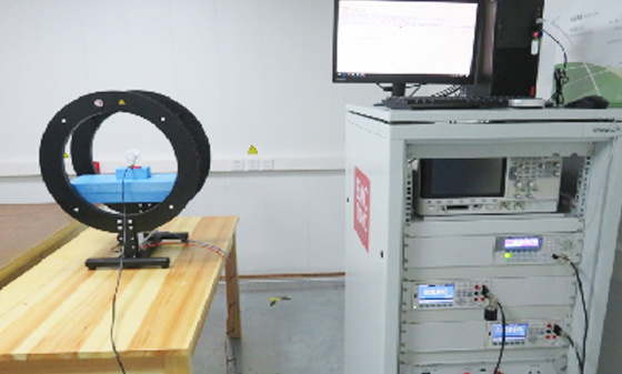 EMS Test - High Current Injection (BCI) Test
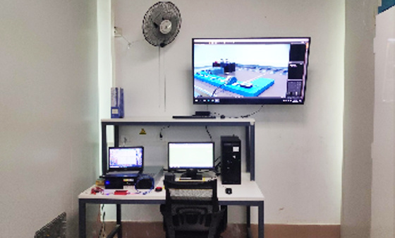 EMS test - low-frequency magnetic field anti-interference test
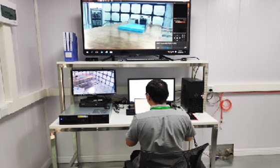 EMI Testing - Transient Conducted Emissions Testing System
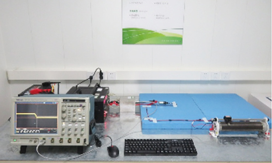 EMI testing - low-frequency magnetic field emission
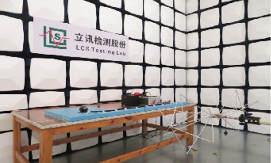 EMI Test - Radiation Emission Test
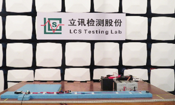 EMI Test - Conducted Emissions Test
 Automotive Electronic Testing
Automotive Parts Inspection
 Automotive ELV&VOC
 Reliability testing
 Temperature shock test
 Vibration testing
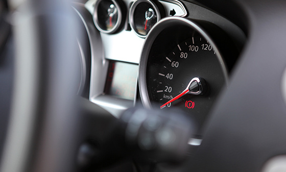 Instrument panel/instrument panel three comprehensive vibration test
 Comprehensive vibration test of door inner panel III
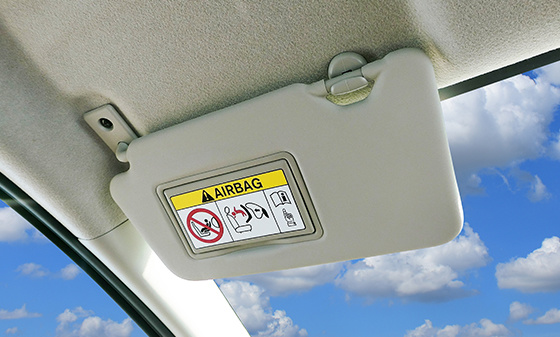 Sunvisor Three Comprehensive Vibration Test
 Spoiler Three Comprehensive Vibration Test
 Three comprehensive vibration tests of car front and rear bumpers
 Three comprehensive vibration tests for lamp housing/lampshade
 Comprehensive vibration test of outer circumference three
 Automotive metal material testing
 Performance testing of automotive lighting fixtures
 Rapid temperature change test
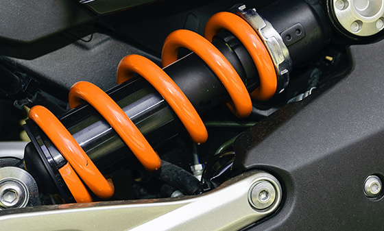 Vibration
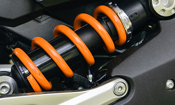 Common issues with vibration testing
 Common issues with fatigue testing
 Common issues with high and low temperature testing
 Conducted Interference (CE) - Suzhou Lixun Standard
 Electromagnetic Radiation Tolerance Test (RS) - Suzhou LCS Standard
 Electrical Fast Pulse Withstand Test (EFT) - Suzhou LCS Standard
 Voltage flicker test - Suzhou LCS standard
Electronic appliances
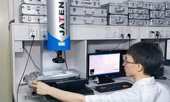 Household appliance product testing
 Electrical accessory product testing
 Household appliance testing
Chemical Testing
 Introduction to PFAS Testing
 MOSH/MOAH Mineral Oil Testing Service
 MOSH/MOAH Mineral Oil Testing and Certification Report Service
 Consumer Product Testing Services - WEEE Chapter
 Ecological textile testing
 Leather Footwear Inspection
 Food contact material testing
 Testing of toys and baby products
 Hazardous substance testing
Electronic Cigarette Testing
 Electronic cigarette detection
Reliability testing
 Other tests - pencil hardness test
 Mechanical testing - Packaging compression test
 Climate environment testing - Xenon lamp aging test
Battery Testing
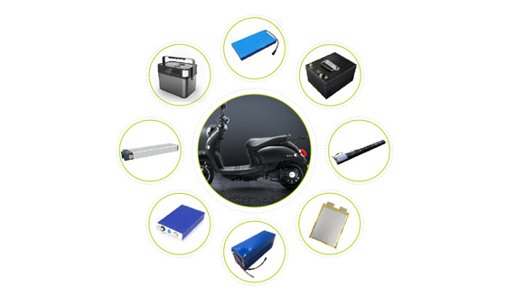 Power storage battery testing and certification
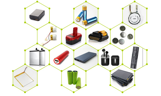 Consumer Electronics Battery Testing and Certification
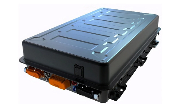 power battery
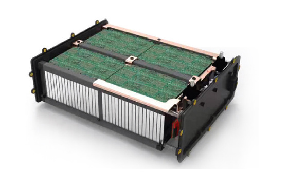 Light electric vehicle batteries
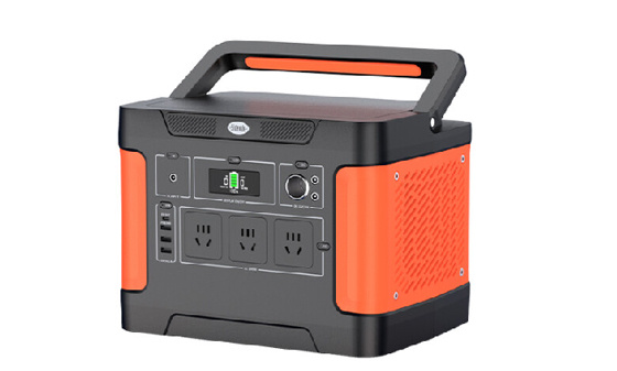 Energy storage battery
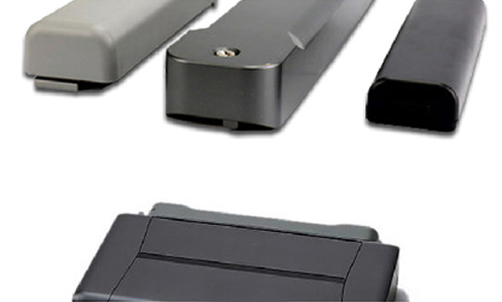 Portable battery
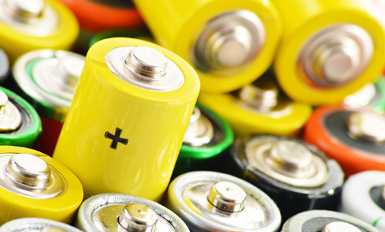 Battery testing
 battery test
Lamp Inspection
 Inspection of ship lighting fixtures
 COI Index Test for Medical Indoor Lighting
 Lamp safety inspection
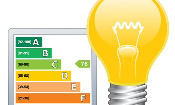 Luminaire energy efficiency testing
 EMC testing of lighting fixtures
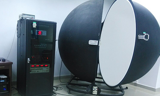 Integral Ball Laboratory
 Photobiology Experiment
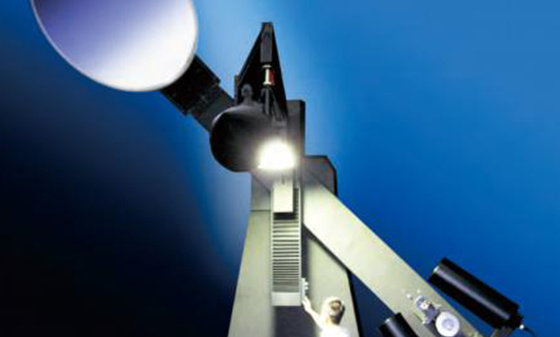 Light distribution test
 Lamp aging test
 Lamp IP waterproof
 Lamp performance testing
 Lamp reliability testing
Children's toy testing
 Testing standards for toy products
China Certification
 China's "national promotion" RoHS certification
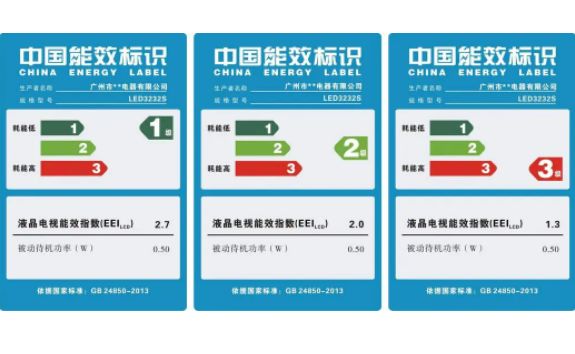 China Energy Efficiency Label Certification
 China Energy Conservation Certification
 China CQC Certification
 Tmall JD Quality Inspection Report
 China SRRC Certification
 Taiwan BSMI certification
 Taiwan NCC certification
 China CCC Compulsory Certification
Asia Certification
 Vietnam certification
 KC certification
 KUCAS Certification in Kuwait
 Singapore PSB certification
 Iraq COC Certification
 IMDA certification
 VCCI Certification in Japan
 JATE certification in Japan
 PSE certification
 BIS certification
 Japanese TELEC certification
European Certification
 RoHS certification
 GOST certification in Russia
 Russian EAC certification
 Northern Ireland UKNI logo
 Electrical ENEC certification
 European D-MARK certification
 Türkiye BTK certification
 TSE certification in Türkiye
 CE certification in Türkiye
 RED certification
 German TUV-SUD certification
 CE-ERP certification
 REACH certification
 German GS certification
 EU E-Mark certification
North American Certification
 Ecuador VOC certification
 Mexico NOM certification
 IRAM certification
 CPSC Certification in the United States
 CSA certification
 ASTM certification
 FDA certification
 CEC certification
 ETL certification
 ul certification
 IC certification
 Energy Star
 FCC Certification in the United States
 ASTM certification
Middle East Certification
 Israel SII certification
 Saudi SABER certification
 GCC certification for the seven Gulf countries
 Iran COI certification
 Qatar COC Certification
 Iraq COC Certification
 Saudi EER Energy Efficiency Certification
 Saudi SABER certification
 Algeria PCA certification
 PVOC certification
Australia Certification
 New Zealand IC-F testing
 VEET certification
 LCP certification
 GEMS certification
 RCM certification
 C-Tick certification
 SAA certification
Africa Certification
 Gabon COC certification
 Algeria COC certification

 Ethiopian VOC and COC certification
 Mauritius VOC certification
 Ghana COC certification
 COC certification in Burundi
 Zambia COC certification
 Botswana COC Certification
 Uganda PVOC certification
 SABS certification in South Africa
 South African LOA certification
 Zimbabwe CBCA Certification
 Nigeria SONCAP certification
 Kenya PVOC certification
 African COC certification
Other certifications
 WEEE
 Bluetooth BQB certification
 IECEE registration
 MHRA registration in the UK
TRAINING
 Management system training
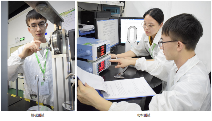 Laboratory technical training
 Laboratory Process Consulting
 Laboratory decoration construction
Wireless Communication
Electromagnetic compatibility
Automotive Electronics
Automotive Parts Inspection
Electronic appliances
Chemical Testing
Electronic Cigarette Testing
Reliability testing
Battery Testing
Lamp Inspection
Children's toy testing
China Certification
Asia Certification
European Certification
North American Certification
Middle East Certification
Australia Certification
Africa Certification
Other certifications
TRAINING

Solutions
-
-
-
Automotive interior and exterior trim - Environmental testing
-
Automotive interior and exterior decorations (electronic and electrical components) - IP protection
-
Automotive electronic and electrical components - Electrical performance
-
Automotive interior and exterior trims - Mechanical performance testing
Contact Us
National 24-hour service hotline
400-116-2629
Group Headquarters
E-mail: webmaster@lcs-cert.com
Address: Shenzhen City, Baoan District, Shajing Street, Nga side of the school of Wei Juji Industrial Park, Building A 1 ~ 2 floor, Building C 3 floor
Grounding resistance test
The equipment grounding should have corresponding good performance, and the grounding resistance should not exceed 100m Ω
The grounding resistance test is a key test to evaluate the performance of the equipment grounding system, ensuring that the equipment is well grounded and the grounding resistance meets the requirements (usually not exceeding 100m Ω), in order to ensure equipment safety and user safety. The following are the key elements and steps of grounding resistance test:
1. Test objectives
Grounding resistance: Measure the resistance between the grounding terminal of the equipment and the ground, ensuring that it does not exceed 100m Ω.
Grounding continuity: Check if the grounding path is complete and ensure there are no open circuits or high impedance points.
Safety: Ensure that the equipment can effectively conduct leakage current under fault conditions, preventing electric shock or fire.
2. Testing conditions
Environmental conditions: Tested in a dry, non corrosive gas environment.
Grounding electrode: Ensure good contact between the grounding electrode and the ground, without rust or looseness.
Equipment status: The equipment is in a power-off state to ensure safe testing.
3. Testing equipment
Grounding resistance tester: used to measure grounding resistance, common models such as Fluke 1625 or Megger DET series.
Test cable: Connect the tester to the equipment grounding terminal and grounding electrode.
Auxiliary electrode: used for current and voltage electrodes in four wire testing.
4. Testing methods
Four line method (recommended)
Arrange electrodes:
Connect the grounding terminal of the device to the C1 terminal of the tester.
Arrange two auxiliary electrodes around the grounding electrode: the current electrode (C2) and the voltage electrode (P2).
The distance between the current electrode (C2) and the grounding electrode should be 3-5 times the length of the grounding electrode.
The voltage pole (P2) is located 62% between the ground electrode and the current pole.
Testing:
Start the grounding resistance tester and inject test current.
Record the grounding resistance value.
Judgment:
The grounding resistance should be ≤ 100m Ω.
Three line method (simplified version)
Arrange electrodes:
Connect the grounding terminal of the device to the C1 terminal of the tester.
Arrange an auxiliary electrode (C2) as the current electrode.
Testing:
Start the tester and inject test current.
Record the grounding resistance value.
Judgment:
The grounding resistance should be ≤ 100m Ω.
5. Testing steps
prepare
Confirm that the device is powered off to ensure safe testing.
Check if the grounding electrode and connecting cable are intact.
Connection tester:
Connect the tester using the four wire or three wire method.
Measurement:
Start the tester and record the grounding resistance value.
Repeated testing:
Repeat the test at different locations to ensure consistency of the results.
Judgment:
Confirm if the grounding resistance is ≤ 100m Ω.
6. Improvement measures
Cleaning the grounding electrode: Remove rust or dirt from the surface of the grounding electrode to reduce contact resistance.
Add grounding electrodes: When the grounding resistance is too high, increase the number or depth of grounding electrodes.
Use drag reducer: Fill the grounding electrode with drag reducer to improve grounding performance.
Check the connection point: Ensure that the grounding wire is firmly connected to the equipment without looseness or corrosion.
7. Common standards
IEC 60364-6: Grounding Test Standard for Low Voltage Electrical Installations.
NFPA 70 (NEC): Requirements for grounding resistance in the National Electrical Code of the United States.
GB 50169: Code for Construction and Acceptance of Grounding Devices in Electrical Equipment Installation Engineering in China.
8. Precautions
Test safety: Ensure that the equipment is powered off to avoid the risk of electric shock.
Environmental factors: Avoid testing in damp or corrosive environments to avoid affecting the results.
Electrode arrangement: Strictly arrange the electrodes according to the four wire or three wire method to ensure testing accuracy.
Regular testing: Regularly conduct grounding resistance testing to ensure the long-term reliability of the grounding system.
Through the grounding resistance test, it can be ensured that the equipment grounding system meets safety requirements, effectively preventing hazards such as electric shock and fire, and ensuring the safety of equipment and users.
Large-scale experimental base
Professional Lab
Analysis Method
Testing/year


 WeChat Inquiry


 Reservation


Contact Us
National 24-hour service hotline
Address:Juji Industrial Park, Xueziwei, Ngabian, Shajing Street, Baoan District, Shenzhen Building A 1~2F, Building C 3F

WeChat public number
Share industry dry goods

WeChat consultation
Please note consulting services

Follow Jitterbug

Mobile website
di complaint mailbox: customer.complaint@lcs-cert.com complaint telephone tel: 18126445450 certificate report verification of authenticity mailbox: verification@lcs-cert.com