

Wireless Communication
 EU RED Network Security Standard EN 18031
 Wireless and communication detection
 Mobile communication product certification
 Bluetooth BQB Product Certification
 FM/AM Product Certification
 WiFi Product Certification
 Wireless charging product certification
 Interphone product certification
 Base station certification
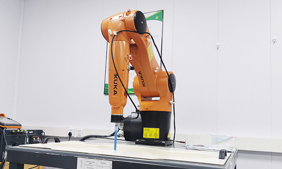 SAR testing
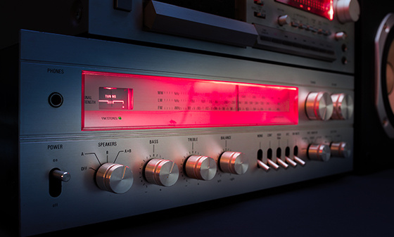 Receiver Product Certification
 5G NR Product Certification
 UWB Product Certification
 Internet of Things authentication
Electromagnetic compatibility
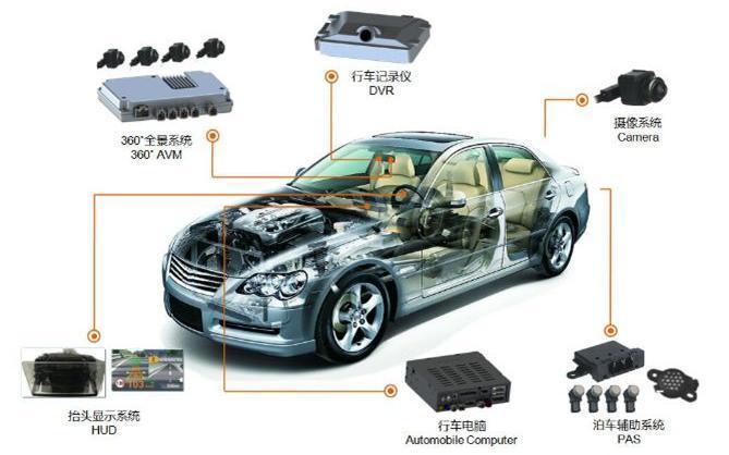 Automotive Electronics EMC Testing
 EMC rectification
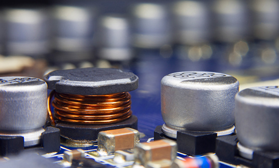 EMC
Automotive Electronics
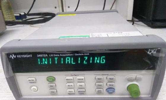 Electrical performance testing
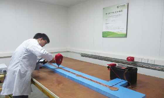 EMS testing - radiation anti-interference testing system (including radar waves)
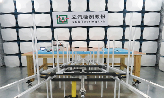 EMS Testing - Electrostatic Discharge
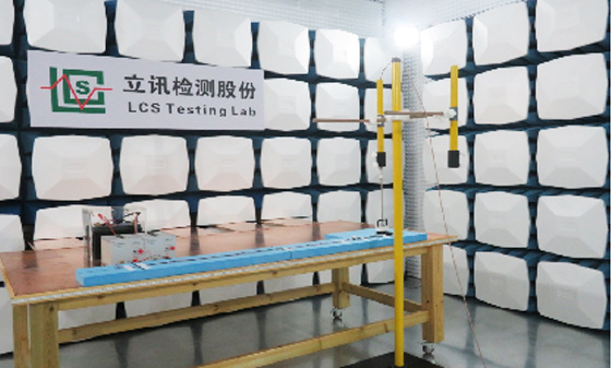 EMS Test - Transient Conducted Immunity Test
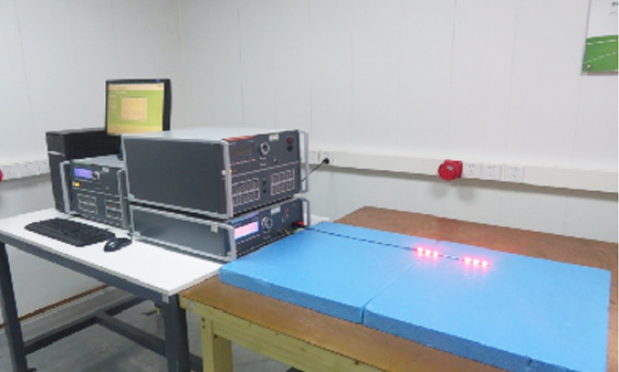 EMS Testing - Portable Transmitter Immunity
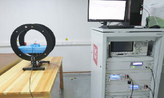 EMS Test - High Current Injection (BCI) Test
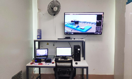 EMS test - low-frequency magnetic field anti-interference test
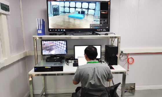 EMI Testing - Transient Conducted Emissions Testing System
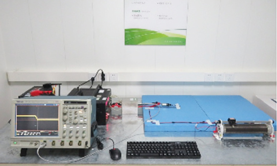 EMI testing - low-frequency magnetic field emission
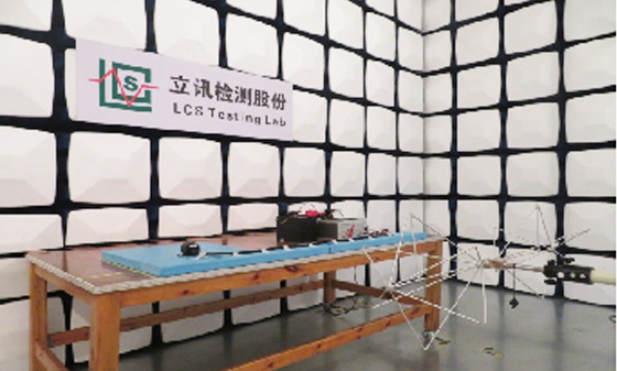 EMI Test - Radiation Emission Test
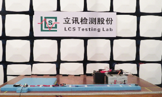 EMI Test - Conducted Emissions Test
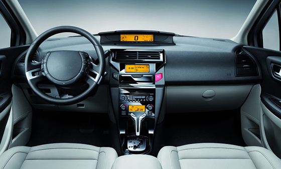 Automotive Electronic Testing
Automotive Parts Inspection
 Automotive ELV&VOC
 Reliability testing
 Temperature shock test
 Vibration testing
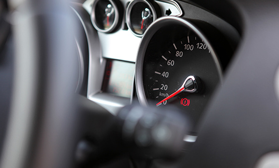 Instrument panel/instrument panel three comprehensive vibration test
 Comprehensive vibration test of door inner panel III
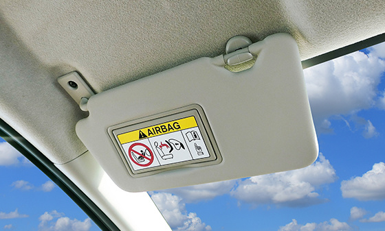 Sunvisor Three Comprehensive Vibration Test
 Spoiler Three Comprehensive Vibration Test
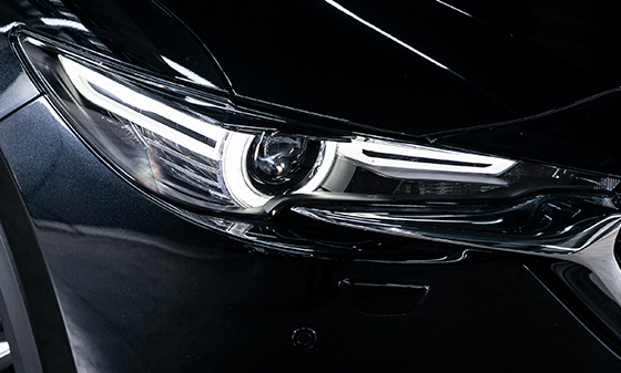 Three comprehensive vibration tests of car front and rear bumpers
 Three comprehensive vibration tests for lamp housing/lampshade
 Comprehensive vibration test of outer circumference three
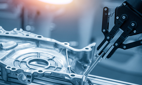 Automotive metal material testing
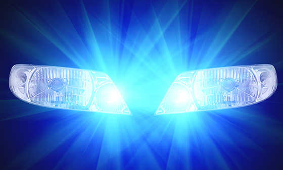 Performance testing of automotive lighting fixtures
 Rapid temperature change test
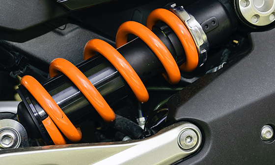 Vibration
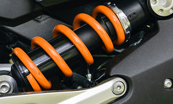 Common issues with vibration testing
 Common issues with fatigue testing
 Common issues with high and low temperature testing
 Conducted Interference (CE) - Suzhou Lixun Standard
 Electromagnetic Radiation Tolerance Test (RS) - Suzhou LCS Standard
 Electrical Fast Pulse Withstand Test (EFT) - Suzhou LCS Standard
 Voltage flicker test - Suzhou LCS standard
Electronic appliances
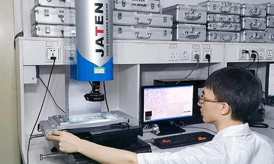 Household appliance product testing
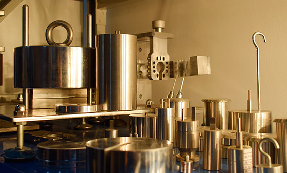 Electrical accessory product testing
 Household appliance testing
Chemical Testing
 Introduction to PFAS Testing
 MOSH/MOAH Mineral Oil Testing Service
 MOSH/MOAH Mineral Oil Testing and Certification Report Service
 Consumer Product Testing Services - WEEE Chapter
 Ecological textile testing
 Leather Footwear Inspection
 Food contact material testing
 Testing of toys and baby products
 Hazardous substance testing
Electronic Cigarette Testing
 Electronic cigarette detection
Reliability testing
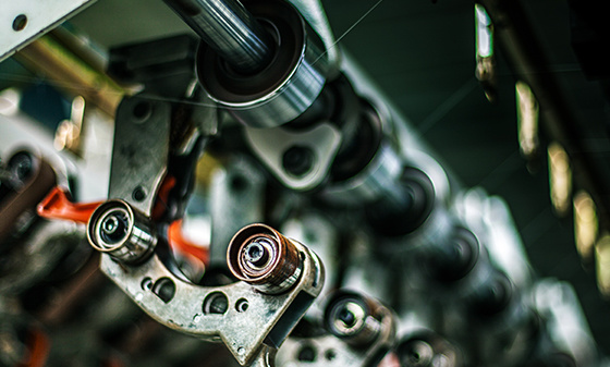 Other tests - pencil hardness test
 Mechanical testing - Packaging compression test
 Climate environment testing - Xenon lamp aging test
Battery Testing
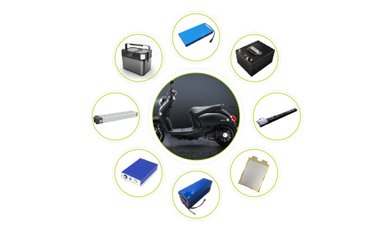 Power storage battery testing and certification
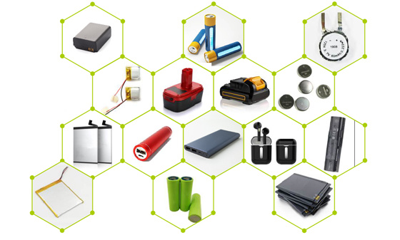 Consumer Electronics Battery Testing and Certification
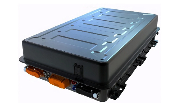 power battery
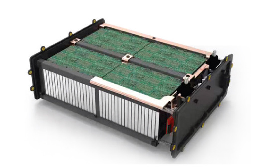 Light electric vehicle batteries
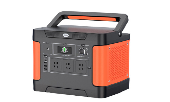 Energy storage battery
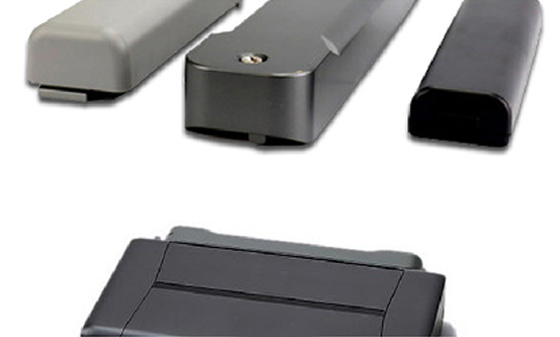 Portable battery
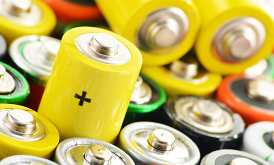 Battery testing
 battery test
Lamp Inspection
 Inspection of ship lighting fixtures
 COI Index Test for Medical Indoor Lighting
 Lamp safety inspection
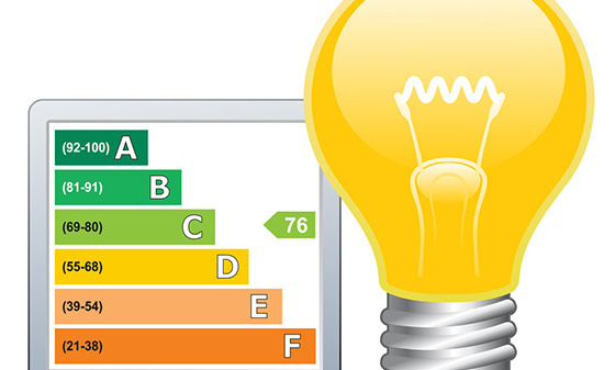 Luminaire energy efficiency testing
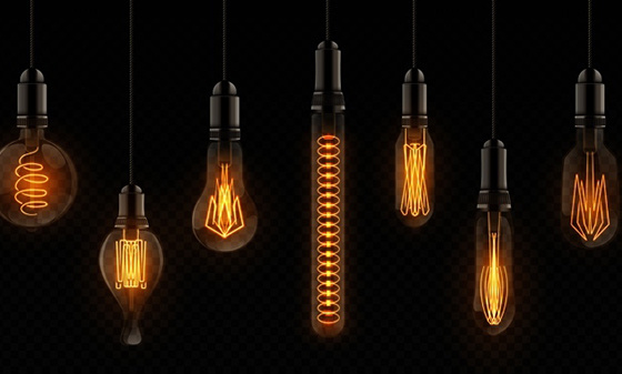 EMC testing of lighting fixtures
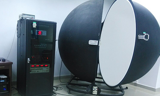 Integral Ball Laboratory
 Photobiology Experiment
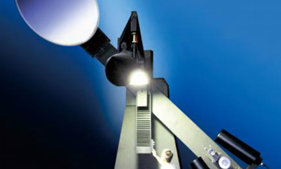 Light distribution test
 Lamp aging test
 Lamp IP waterproof
 Lamp performance testing
 Lamp reliability testing
Children's toy testing
 Testing standards for toy products
China Certification
 China's "national promotion" RoHS certification
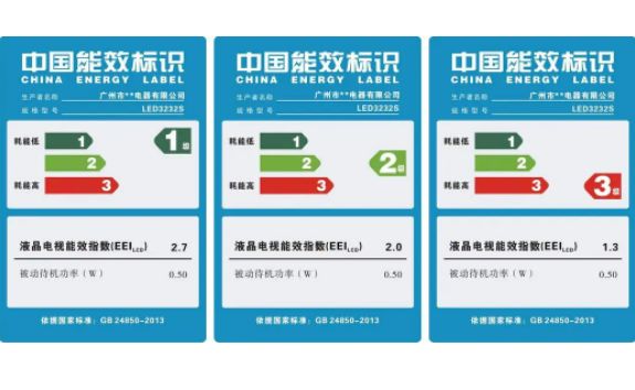 China Energy Efficiency Label Certification
 China Energy Conservation Certification
 China CQC Certification
 Tmall JD Quality Inspection Report
 China SRRC Certification
 Taiwan BSMI certification
 Taiwan NCC certification
 China CCC Compulsory Certification
Asia Certification
 Vietnam certification
 KC certification
 KUCAS Certification in Kuwait
 Singapore PSB certification
 Iraq COC Certification
 IMDA certification
 VCCI Certification in Japan
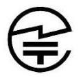 JATE certification in Japan
 PSE certification
 BIS certification
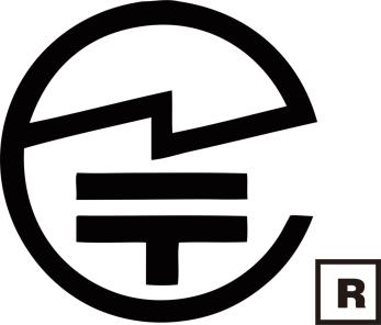 Japanese TELEC certification
European Certification
 RoHS certification
 GOST certification in Russia
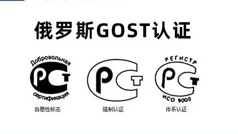 Russian EAC certification
 Northern Ireland UKNI logo
 Electrical ENEC certification
 European D-MARK certification
 Türkiye BTK certification
 TSE certification in Türkiye
 CE certification in Türkiye
 RED certification
 German TUV-SUD certification
 CE-ERP certification
 REACH certification
 German GS certification
 EU E-Mark certification
North American Certification
 Ecuador VOC certification
 Mexico NOM certification
 IRAM certification
 CPSC Certification in the United States
 CSA certification
 ASTM certification
 FDA certification
 CEC certification
 ETL certification
 ul certification
 IC certification
 Energy Star
 FCC Certification in the United States
 ASTM certification
Middle East Certification
 Israel SII certification
 Saudi SABER certification
 GCC certification for the seven Gulf countries
 Iran COI certification
 Qatar COC Certification
 Iraq COC Certification
 Saudi EER Energy Efficiency Certification
 Saudi SABER certification
 Algeria PCA certification
 PVOC certification
Australia Certification
 New Zealand IC-F testing
 VEET certification
 LCP certification
 GEMS certification
 RCM certification
 C-Tick certification
 SAA certification
Africa Certification
 Gabon COC certification
 Algeria COC certification

 Ethiopian VOC and COC certification
 Mauritius VOC certification
 Ghana COC certification
 COC certification in Burundi
 Zambia COC certification
 Botswana COC Certification
 Uganda PVOC certification
 SABS certification in South Africa
 South African LOA certification
 Zimbabwe CBCA Certification
 Nigeria SONCAP certification
 Kenya PVOC certification
 African COC certification
Other certifications
 WEEE
 Bluetooth BQB certification
 IECEE registration
 MHRA registration in the UK
TRAINING
 Management system training
 Laboratory technical training
 Laboratory Process Consulting
 Laboratory decoration construction
Wireless Communication
Electromagnetic compatibility
Automotive Electronics
Automotive Parts Inspection
Electronic appliances
Chemical Testing
Electronic Cigarette Testing
Reliability testing
Battery Testing
Lamp Inspection
Children's toy testing
China Certification
Asia Certification
European Certification
North American Certification
Middle East Certification
Australia Certification
Africa Certification
Other certifications
TRAINING

Solutions
-
-
-
Automotive interior and exterior trim - Environmental testing
-
Automotive interior and exterior decorations (electronic and electrical components) - IP protection
-
Automotive electronic and electrical components - Electrical performance
-
Automotive interior and exterior trims - Mechanical performance testing
Contact Us
National 24-hour service hotline
400-116-2629
Group Headquarters
E-mail: webmaster@lcs-cert.com
Address: Shenzhen City, Baoan District, Shajing Street, Nga side of the school of Wei Juji Industrial Park, Building A 1 ~ 2 floor, Building C 3 floor
Transient coupling anti-interference test
ISO7637-3 Part 3: Electrical transient emission through capacitive and inductive coupling of wires other than power lines
Experimental pulse simulation of fast transient disturbances and slow transient disturbances, such as transient disturbances caused by inductive load switching, relay contact jumping, etc. There are three methods in total: capacitive coupling clamp (CCC) method, direct capacitive coupling (DCC) method, and inductive coupling clamp (ICC) method. Only one method needs to be selected for slow electrical transient test and fast transient test;
Overview
ISO 7637-3 is a test standard used to evaluate the immunity of automotive electronic devices to electrical transient emissions through capacitive and inductive coupling on wires other than power lines. This standard simulates fast transient disturbances and slow transient disturbances (such as transient disturbances caused by inductive load switching, relay contact jumping, etc.), and provides three testing methods: capacitive coupling clamp (CCC) method, direct capacitive coupling (DCC) method, and inductive coupling clamp (ICC) method.
Test purpose
Evaluate the immunity performance of automotive electronic devices to electrical transient emissions through capacitive and inductive coupling on wires other than power lines.
Ensure that the equipment can withstand transient disturbances in the actual working environment.
Identify potential failure risks of devices in transient disturbance environments.
test method
ISO 7637-3 provides three testing methods, slow electrical transient test and fast transient test. Only one method needs to be selected for testing.
1. Capacitive Coupling Clamp (CCC) method
Principle: The transient disturbance signal is coupled to the signal line of the device under test through a capacitive coupling clamp.
Applicable scenario: Suitable for transient disturbance testing of signal lines.
Advantages: Non contact testing, which will not cause physical damage to signal lines.
2. Direct Capacitive Coupling (DCC) method
Principle: Inject transient disturbance signals into the signal line of the device under test through direct capacitive coupling.
Applicable scenario: Suitable for transient disturbance testing of signal lines.
Advantages: Direct injection, high coupling efficiency.
3. Inductive Coupled Clamp (ICC) method
Principle: The transient disturbance signal is coupled to the signal line of the device under test through an inductive coupling clamp.
Applicable scenario: Suitable for transient disturbance testing of signal lines.
Advantages: Non contact testing, suitable for high-frequency transient disturbances.
Test steps
Preparation:
Install the device under test (DUT) on the test bench and connect all necessary cables and power sources.
Ensure that the equipment is in normal working condition.
Select testing method:
Select the capacitive coupling clamp (CCC) method, direct capacitive coupling (DCC) method, or inductive coupling clamp (ICC) method according to the testing requirements.
Set up testing environment:
Install testing equipment (such as signal generators, coupling clamps, etc.) in the shielding room or testing platform.
Calibrate testing equipment to ensure the accuracy of testing conditions.
Conduct testing:
Start the tested device and put it in typical working mode.
Generate transient disturbance signals with specific waveforms and intensities using a signal generator.
Inject transient disturbance signals into the signal line of the tested device through the selected coupling method.
Observe the performance changes of the equipment and record any abnormalities or malfunctions.
data analysis
Analyze test data and evaluate the anti-interference performance of the equipment.
Determine whether the equipment is qualified according to the standard limit.
test conditions
Transient disturbance waveform:
Slow transient disturbance: Simulate transient disturbances caused by inductive load conversion, etc.
Fast transient disturbance: Simulate transient disturbances caused by relay contact jumping, etc.
Test voltage: usually between 10 V and 100 V, depending on the testing standards and application scenarios.
Testing time: Each testing point lasts from a few seconds to a few minutes, depending on the testing standards.
Precautions
Test environment: Ensure that there is no external interference in the shielded room or test bench.
Equipment status: Ensure that the tested equipment is in a typical working state, covering all possible working modes.
Coupling method selection: Choose the appropriate coupling method according to the testing requirements to ensure the accuracy of the testing conditions.
Safety protection: During the testing process, attention should be paid to the potential impact of high-voltage transient signals on the human body and necessary protective measures should be taken.
Common problems and solutions
Equipment performance degradation:
Reason: Unreasonable circuit design, insufficient shielding, inadequate filtering, etc.
Solution: Optimize circuit design, add shielding measures, and use filters.
The test results are unstable:
Reason: External interference, unstable device operation status.
Solution: Test in a shielded environment to ensure consistent device operation.
Application field
Automotive electronics: in car entertainment systems, engine control units (ECUs), sensors, etc.
Industrial electronics: industrial controllers, motor drivers, etc.
Consumer electronics: smart devices, household appliances, etc.
Conclusion
The testing of ISO 7637-3 Part III is an important means of evaluating the immunity performance of automotive electronic devices to electrical transient emissions through capacitive and inductive coupling on wires other than power lines. By simulating transient disturbances in real environments, potential risks of equipment in actual working environments can be identified and necessary improvement measures can be taken. During the testing process, attention should be paid to the testing environment, equipment status, and coupling method selection to ensure the accuracy and reliability of the test results.
Large-scale experimental base
Professional Lab
Analysis Method
Testing/year


 WeChat Inquiry


 Reservation


Contact Us
National 24-hour service hotline
Address:Juji Industrial Park, Xueziwei, Ngabian, Shajing Street, Baoan District, Shenzhen Building A 1~2F, Building C 3F

WeChat public number
Share industry dry goods

WeChat consultation
Please note consulting services

Follow Jitterbug

Mobile website
di complaint mailbox: customer.complaint@lcs-cert.com complaint telephone tel: 18126445450 certificate report verification of authenticity mailbox: verification@lcs-cert.com