

Wireless Communication
 EU RED Network Security Standard EN 18031
 Wireless and communication detection
 Mobile communication product certification
 Bluetooth BQB Product Certification
 FM/AM Product Certification
 WiFi Product Certification
 Wireless charging product certification
 Interphone product certification
 Base station certification
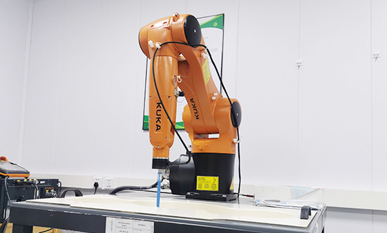 SAR testing
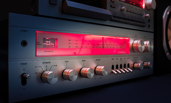 Receiver Product Certification
 5G NR Product Certification
 UWB Product Certification
 Internet of Things authentication
Electromagnetic compatibility
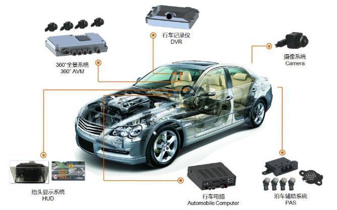 Automotive Electronics EMC Testing
 EMC rectification
 EMC
EMC
Automotive Electronics
 Electrical performance testing
 EMS testing - radiation anti-interference testing system (including radar waves)
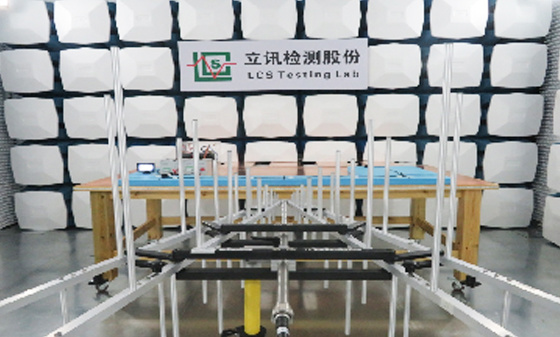 EMS Testing - Electrostatic Discharge
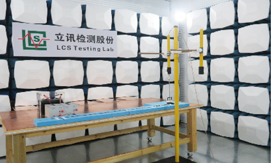 EMS Test - Transient Conducted Immunity Test
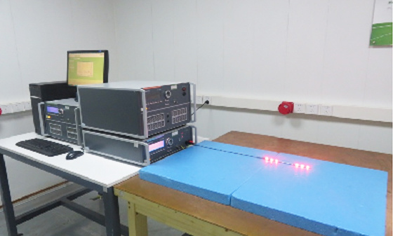 EMS Testing - Portable Transmitter Immunity
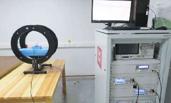 EMS Test - High Current Injection (BCI) Test
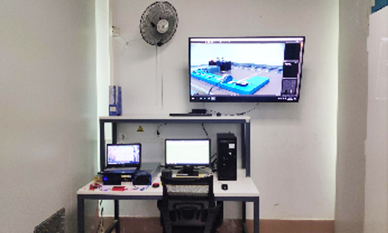 EMS test - low-frequency magnetic field anti-interference test
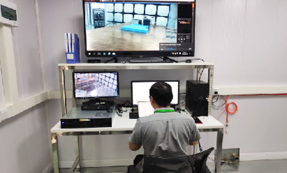 EMI Testing - Transient Conducted Emissions Testing System
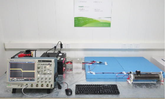 EMI testing - low-frequency magnetic field emission
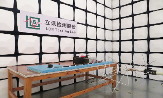 EMI Test - Radiation Emission Test
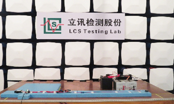 EMI Test - Conducted Emissions Test
 Automotive Electronic Testing
Automotive Parts Inspection
 Automotive ELV&VOC
 Reliability testing
 Temperature shock test
 Vibration testing
 Instrument panel/instrument panel three comprehensive vibration test
 Comprehensive vibration test of door inner panel III
 Sunvisor Three Comprehensive Vibration Test
 Spoiler Three Comprehensive Vibration Test
 Three comprehensive vibration tests of car front and rear bumpers
 Three comprehensive vibration tests for lamp housing/lampshade
 Comprehensive vibration test of outer circumference three
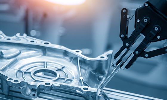 Automotive metal material testing
 Performance testing of automotive lighting fixtures
 Rapid temperature change test
 Vibration
 Common issues with vibration testing
 Common issues with fatigue testing
 Common issues with high and low temperature testing
 Conducted Interference (CE) - Suzhou Lixun Standard
 Electromagnetic Radiation Tolerance Test (RS) - Suzhou LCS Standard
 Electrical Fast Pulse Withstand Test (EFT) - Suzhou LCS Standard
 Voltage flicker test - Suzhou LCS standard
Electronic appliances
 Household appliance product testing
 Electrical accessory product testing
 Household appliance testing
Chemical Testing
 Introduction to PFAS Testing
 MOSH/MOAH Mineral Oil Testing Service
 MOSH/MOAH Mineral Oil Testing and Certification Report Service
 Consumer Product Testing Services - WEEE Chapter
 Ecological textile testing
 Leather Footwear Inspection
 Food contact material testing
 Testing of toys and baby products
 Hazardous substance testing
Electronic Cigarette Testing
 Electronic cigarette detection
Reliability testing
 Other tests - pencil hardness test
 Mechanical testing - Packaging compression test
 Climate environment testing - Xenon lamp aging test
Battery Testing
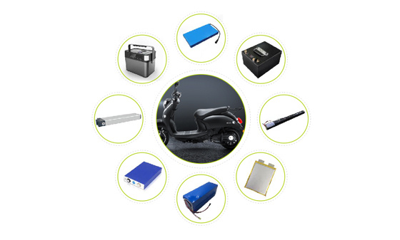 Power storage battery testing and certification
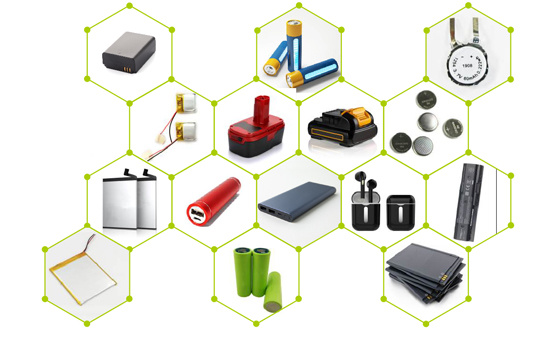 Consumer Electronics Battery Testing and Certification
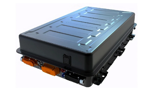 power battery
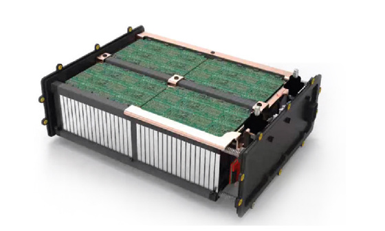 Light electric vehicle batteries
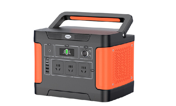 Energy storage battery
 Portable battery
 Battery testing
 battery test
Lamp Inspection
 Inspection of ship lighting fixtures
 COI Index Test for Medical Indoor Lighting
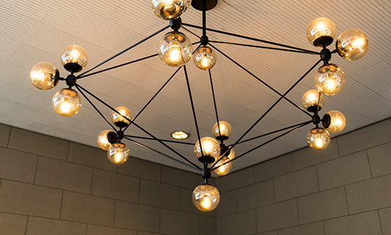 Lamp safety inspection
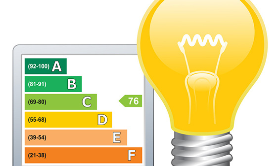 Luminaire energy efficiency testing
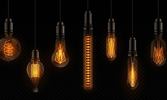 EMC testing of lighting fixtures
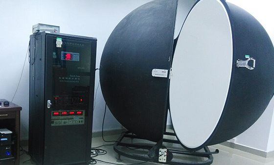 Integral Ball Laboratory
 Photobiology Experiment
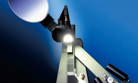 Light distribution test
 Lamp aging test
 Lamp IP waterproof
 Lamp performance testing
 Lamp reliability testing
Children's toy testing
 Testing standards for toy products
China Certification
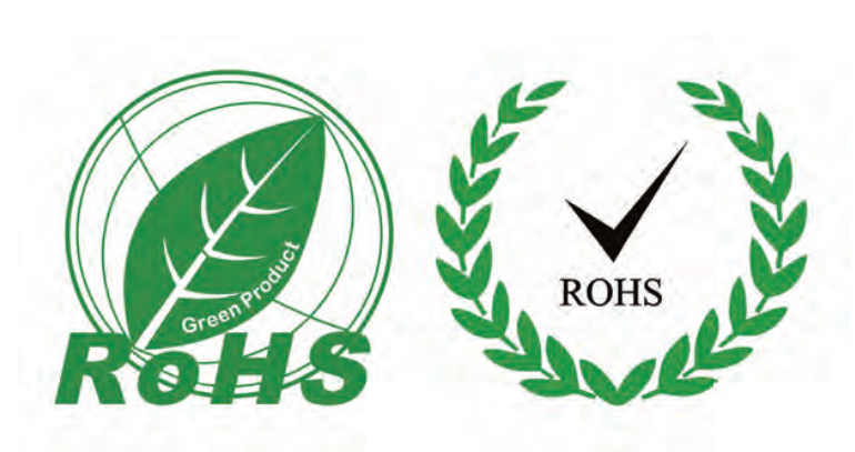 China's "national promotion" RoHS certification
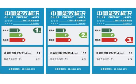 China Energy Efficiency Label Certification
 China Energy Conservation Certification
 China CQC Certification
 Tmall JD Quality Inspection Report
 China SRRC Certification
 Taiwan BSMI certification
 Taiwan NCC certification
 China CCC Compulsory Certification
Asia Certification
 Vietnam certification
 KC certification
 KUCAS Certification in Kuwait
 Singapore PSB certification
 Iraq COC Certification
 IMDA certification
 VCCI Certification in Japan
 JATE certification in Japan
 PSE certification
 BIS certification
 Japanese TELEC certification
European Certification
 RoHS certification
 GOST certification in Russia
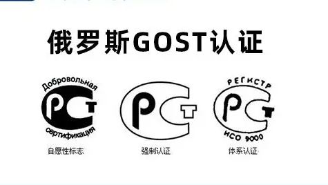 Russian EAC certification
 Northern Ireland UKNI logo
 Electrical ENEC certification
 European D-MARK certification
 Türkiye BTK certification
 TSE certification in Türkiye
 CE certification in Türkiye
 RED certification
 German TUV-SUD certification
 CE-ERP certification
 REACH certification
 German GS certification
 EU E-Mark certification
North American Certification
 Ecuador VOC certification
 Mexico NOM certification
 IRAM certification
 CPSC Certification in the United States
 CSA certification
 ASTM certification
 FDA certification
 CEC certification
 ETL certification
 ul certification
 IC certification
 Energy Star
 FCC Certification in the United States
 ASTM certification
Middle East Certification
 Israel SII certification
 Saudi SABER certification
 GCC certification for the seven Gulf countries
 Iran COI certification
 Qatar COC Certification
 Iraq COC Certification
 Saudi EER Energy Efficiency Certification
 Saudi SABER certification
 Algeria PCA certification
 PVOC certification
Australia Certification
 New Zealand IC-F testing
 VEET certification
 LCP certification
 GEMS certification
 RCM certification
 C-Tick certification
 SAA certification
Africa Certification
 Gabon COC certification
 Algeria COC certification

 Ethiopian VOC and COC certification
 Mauritius VOC certification
 Ghana COC certification
 COC certification in Burundi
 Zambia COC certification
 Botswana COC Certification
 Uganda PVOC certification
 SABS certification in South Africa
 South African LOA certification
 Zimbabwe CBCA Certification
 Nigeria SONCAP certification
 Kenya PVOC certification
 African COC certification
Other certifications
 WEEE
WEEE
 Bluetooth BQB certification
 IECEE registration
 MHRA registration in the UK
TRAINING
 Management system training
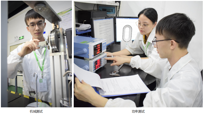 Laboratory technical training
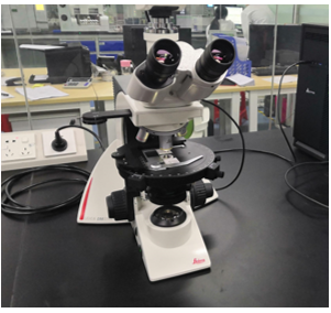 Laboratory Process Consulting
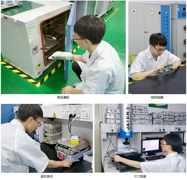 Laboratory decoration construction
Wireless Communication
Electromagnetic compatibility
Automotive Electronics
Automotive Parts Inspection
Electronic appliances
Chemical Testing
Electronic Cigarette Testing
Reliability testing
Battery Testing
Lamp Inspection
Children's toy testing
China Certification
Asia Certification
European Certification
North American Certification
Middle East Certification
Australia Certification
Africa Certification
Other certifications
TRAINING
Wireless Communication
Electromagnetic compatibility
Automotive Electronics
Automotive Parts Inspection
Electronic appliances
Chemical Testing
Electronic Cigarette Testing
Reliability testing
Battery Testing
Lamp Inspection
Children's toy testing
China Certification
Asia Certification
European Certification
North American Certification
Middle East Certification
Australia Certification
Africa Certification
Other certifications
TRAINING
Wireless Communication
Electromagnetic compatibility
Automotive Electronics
Automotive Parts Inspection
Electronic appliances
Chemical Testing
Electronic Cigarette Testing
Reliability testing
Battery Testing
Lamp Inspection
Children's toy testing
China Certification
Asia Certification
European Certification
North American Certification
Middle East Certification
Australia Certification
Africa Certification
Other certifications
TRAINING
Wireless Communication
Electromagnetic compatibility
Automotive Electronics
Automotive Parts Inspection
Electronic appliances
Chemical Testing
Electronic Cigarette Testing
Reliability testing
Battery Testing
Lamp Inspection
Children's toy testing
China Certification
Asia Certification
European Certification
North American Certification
Middle East Certification
Australia Certification
Africa Certification
Other certifications
TRAINING
Wireless Communication
Electromagnetic compatibility
Automotive Electronics
Automotive Parts Inspection
Electronic appliances
Chemical Testing
Electronic Cigarette Testing
Reliability testing
Battery Testing
Lamp Inspection
Children's toy testing
China Certification
Asia Certification
European Certification
North American Certification
Middle East Certification
Australia Certification
Africa Certification
Other certifications
TRAINING
Wireless Communication
Electromagnetic compatibility
Automotive Electronics
Automotive Parts Inspection
Electronic appliances
Chemical Testing
Electronic Cigarette Testing
Reliability testing
Battery Testing
Lamp Inspection
Children's toy testing
China Certification
Asia Certification
European Certification
North American Certification
Middle East Certification
Australia Certification
Africa Certification
Other certifications
TRAINING

Introduction to EMC filtering
Author.
LCS
Source:
Post time:
2026-04-02
In PCB design, filtering is essential: on the one hand, other methods cannot completely suppress the conducted noise entering and exiting the equipment. When electrical signals enter and exit the equipment, effective filtering must be carried out; On the other hand, changes in the output state of integrated chips or other reasons can generate certain noise on the chip's power supply, which can affect the normal operation of the chip itself or other chips. Filtering measures are essential and the most commonly used countermeasures. In principle design, many filtering measures are often taken into account, such as decoupling capacitors, three terminal capacitors, magnetic beads, power filtering, interface filtering, etc. However, in PCB design, if the position of the filtering device is not properly placed, the filtering effect will be greatly reduced, and even the filtering effect will not be achieved.
The general consideration for installing filter components is the principle of proximity. For example:
Decoupling capacitors should be placed as close as possible to the power pins of the IC;
Power filtering should be placed as close as possible to the power input or output;
The filtering of local functional modules should be close to the entrance of the module;
The filtering of external interfaces (such as magnetic beads) should be placed as close as possible to the connectors.
There are many commonly used filtering devices, including resistors, inductors, capacitors, ferrite beads, etc.
1、 Resistance
Resistors cannot be used alone for filtering purposes. They are generally combined with capacitors to form RC filters.
The characteristics of resistors are shown in the following figure. Due to the presence of lead inductance (ESL) and parasitic capacitance, there are significant differences in the high and low frequency characteristics of resistors, which should be taken into account when designing filters.

2、 Inductance
The high and low frequency characteristics of the inductor are shown in the above figure. Due to the presence of lead resistance (ESR) and parasitic capacitance, the inductance has a self resonant frequency f. The inductance exhibits characteristics of inductance in the frequency range below f. However, in the frequency range above f., it exhibits characteristics of capacitance. This is something that needs special attention when calculating the insertion loss of a filter.
3、 Ferrite magnetic beads
Ferrite magnetic beads are also commonly used devices for filtering. Ferrite used for electromagnetic noise suppression is a magnetic material composed of a mixture of iron, nickel, and zinc oxides, with high electrical resistivity and high magnetic permeability (approximately 100-1500). Ferrite magnetic beads are connected in series on the signal or power path to suppress differential mode noise. When current flows through ferrite, low-frequency current can flow almost without attenuation, but high-frequency current will suffer significant losses and be converted into heat dissipation. Ferrite magnetic beads can be equivalent to a series connection of resistance and inductance, but both the resistance and inductance values vary with frequency. The frequency characteristics of typical ferrite magnetic beads are shown in the figure.

Ferrite magnetic beads have better high-frequency filtering characteristics compared to ordinary inductors. Ferrite exhibits resistance at high frequencies, equivalent to an inductor with a very low quality factor, so it can maintain high impedance over a wide frequency range, thereby improving high-frequency filtering efficiency.
4、 Common mode inductor
Inserting the transmission wire into the center can simultaneously suppress the common mode high-frequency noise of each wire to ground. The usual practice is to wrap two identical coils around the same ferrite ring, where the ferrite magnetic loss is small. The winding method allows the magnetic flux in the magnetic ring of the two coils to overlap with each other when a common mode current flows through them, thereby having a considerable inductance and suppressing the common mode current. However, when the two coils flow through a differential mode current, the magnetic flux in the magnetic ring cancels each other out, with almost no inductance, so the differential mode current can pass through without attenuation.

5、 Capacitor
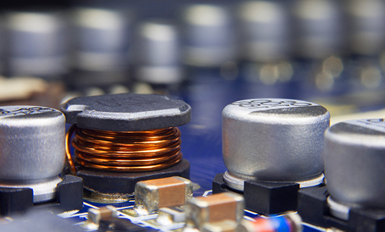
Capacitors are the most widely used components in EMC design of PCBs. Capacitors can be divided into three types based on their functions:
Decouple: Breaking the coupling between ports of a system or circuit to ensure normal operation.
Bypass: Provide a low impedance path to ground where transient energy is generated. It is one of the essential conditions for good decoupling.
Energy storage (Bulk): Energy storage capacitors can ensure that the voltage does not drop when the load quickly becomes heaviest.
For EMI filters, the dielectric material requirements for capacitors are not high; The absolute capacitance value, temperature coefficient of the capacitor, and voltage variation coefficient are usually not important.
In EMC design, the function of filtering is basically to attenuate high-frequency noise, so filters are usually designed as low-pass filters. The typical structural form of the filtering circuit is shown in the following figure:

Related articles
New articles
Media Center
Latest News
Contact Us
National 24-hour service hotline
400-116-2629
Group Headquarters
E-mail: webmaster@lcs-cert.com
Address: Shenzhen City, Baoan District, Shajing Street, Nga side of the school of Wei Juji Industrial Park, Building A 1 ~ 2 floor, Building C 3 floor


 WeChat Inquiry


 Reservation


Contact Us
National 24-hour service hotline
Address:Juji Industrial Park, Xueziwei, Ngabian, Shajing Street, Baoan District, Shenzhen Building A 1~2F, Building C 3F

WeChat public number
Share industry dry goods

WeChat consultation
Please note consulting services

Follow Jitterbug

Mobile website
di complaint mailbox: customer.complaint@lcs-cert.com complaint telephone tel: 18126445450 certificate report verification of authenticity mailbox: verification@lcs-cert.com