

Wireless Communication
 EU RED Network Security Standard EN 18031
 Wireless and communication detection
 Mobile communication product certification
 Bluetooth BQB Product Certification
 FM/AM Product Certification
 WiFi Product Certification
 Wireless charging product certification
 Interphone product certification
 Base station certification
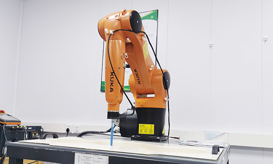 SAR testing
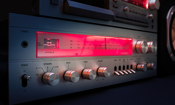 Receiver Product Certification
 5G NR Product Certification
 UWB Product Certification
 Internet of Things authentication
Electromagnetic compatibility
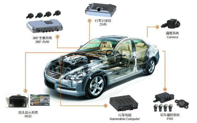 Automotive Electronics EMC Testing
 EMC rectification
 EMC
EMC
Automotive Electronics
 Electrical performance testing
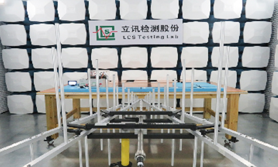
 EMS testing - radiation anti-interference testing system (including radar waves)
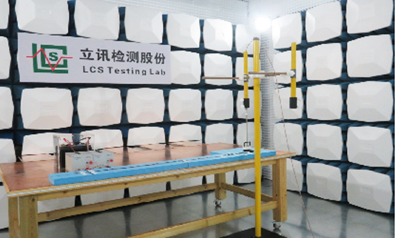
 EMS Testing - Electrostatic Discharge
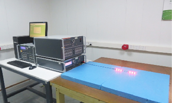
 EMS Test - Transient Conducted Immunity Test
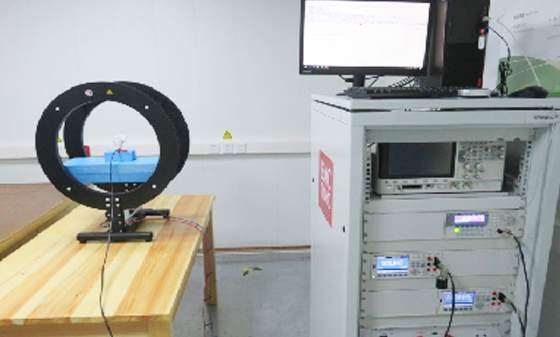
 EMS Testing - Portable Transmitter Immunity
 EMS Test - High Current Injection (BCI) Test
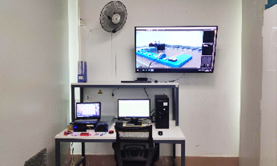 EMS test - low-frequency magnetic field anti-interference test
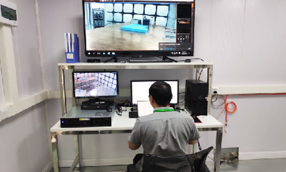 EMI Testing - Transient Conducted Emissions Testing System
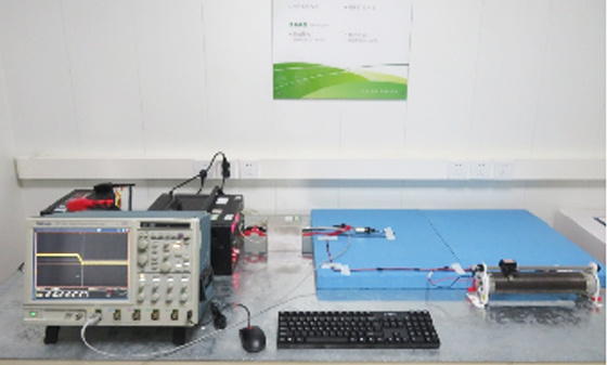 EMI testing - low-frequency magnetic field emission
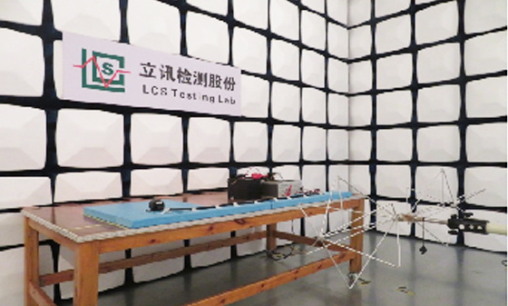 EMI Test - Radiation Emission Test
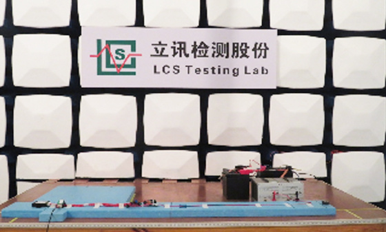 EMI Test - Conducted Emissions Test
 Automotive Electronic Testing
Automotive Parts Inspection
 Automotive ELV&VOC
 Reliability testing
 Temperature shock test
 Vibration testing
 Instrument panel/instrument panel three comprehensive vibration test
 Comprehensive vibration test of door inner panel III
 Sunvisor Three Comprehensive Vibration Test
 Spoiler Three Comprehensive Vibration Test
 Three comprehensive vibration tests of car front and rear bumpers
 Three comprehensive vibration tests for lamp housing/lampshade
 Comprehensive vibration test of outer circumference three
 Automotive metal material testing
 Performance testing of automotive lighting fixtures
 Rapid temperature change test
 Vibration
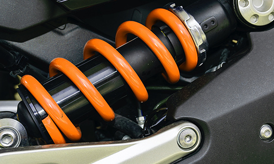 Common issues with vibration testing
 Common issues with fatigue testing
 Common issues with high and low temperature testing
 Conducted Interference (CE) - Suzhou Lixun Standard
 Electromagnetic Radiation Tolerance Test (RS) - Suzhou LCS Standard
 Electrical Fast Pulse Withstand Test (EFT) - Suzhou LCS Standard
 Voltage flicker test - Suzhou LCS standard
Electronic appliances
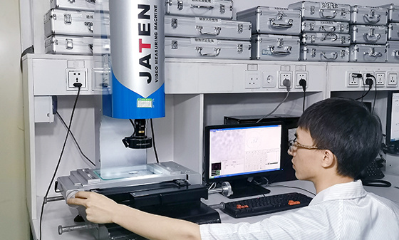 Household appliance product testing
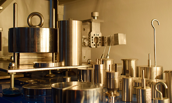 Electrical accessory product testing
 Household appliance testing
Chemical Testing
 Introduction to PFAS Testing
 MOSH/MOAH Mineral Oil Testing Service
 MOSH/MOAH Mineral Oil Testing and Certification Report Service
 Consumer Product Testing Services - WEEE Chapter
 Ecological textile testing
 Leather Footwear Inspection
 Food contact material testing
 Testing of toys and baby products
 Hazardous substance testing
Electronic Cigarette Testing
 Electronic cigarette detection
Reliability testing
 Other tests - pencil hardness test
 Mechanical testing - Packaging compression test
 Climate environment testing - Xenon lamp aging test
Battery Testing
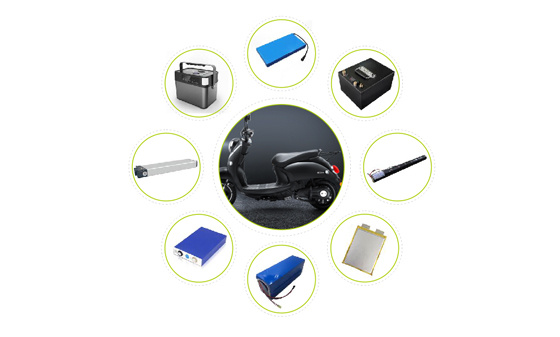 Power storage battery testing and certification
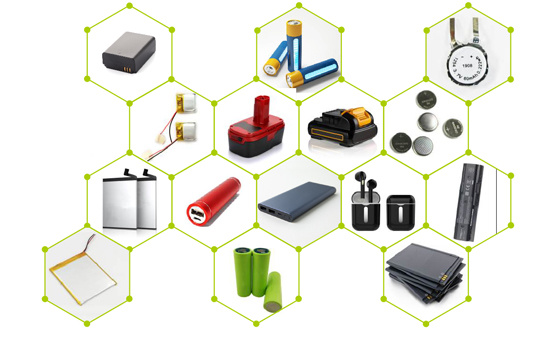 Consumer Electronics Battery Testing and Certification
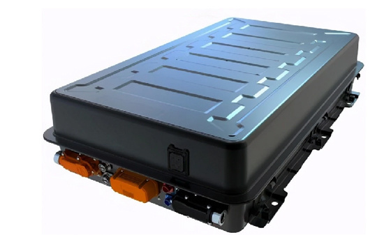 power battery
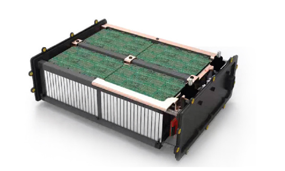 Light electric vehicle batteries
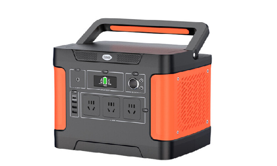 Energy storage battery
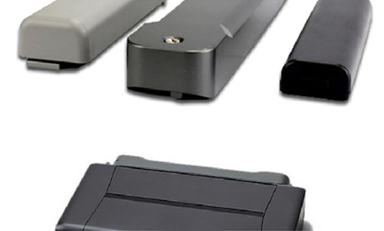 Portable battery
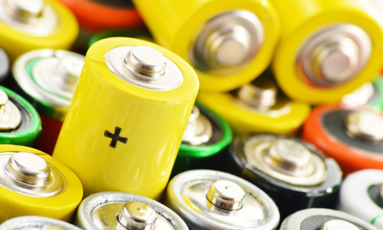 Battery testing
 battery test
Lamp Inspection
 Inspection of ship lighting fixtures
 COI Index Test for Medical Indoor Lighting
 Lamp safety inspection
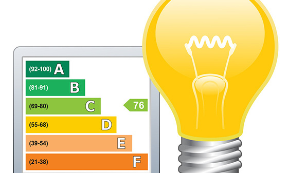 Luminaire energy efficiency testing
 EMC testing of lighting fixtures
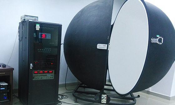 Integral Ball Laboratory
 Photobiology Experiment
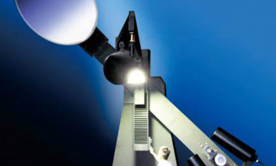 Light distribution test
 Lamp aging test
 Lamp IP waterproof
 Lamp performance testing
 Lamp reliability testing
Children's toy testing
 Testing standards for toy products
China Certification
 China's "national promotion" RoHS certification
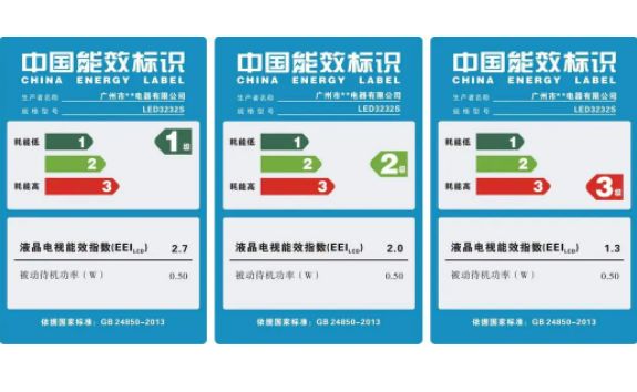 China Energy Efficiency Label Certification
 China Energy Conservation Certification
 China CQC Certification
 Tmall JD Quality Inspection Report
 China SRRC Certification
 Taiwan BSMI certification
 Taiwan NCC certification
 China CCC Compulsory Certification
Asia Certification
 Vietnam certification
 KC certification
 KUCAS Certification in Kuwait
 Singapore PSB certification
 Iraq COC Certification
 IMDA certification
 VCCI Certification in Japan
 JATE certification in Japan
 PSE certification
 BIS certification
 Japanese TELEC certification
European Certification
 RoHS certification
 GOST certification in Russia
 Russian EAC certification
 Northern Ireland UKNI logo
 Electrical ENEC certification
 European D-MARK certification
 Türkiye BTK certification
 TSE certification in Türkiye
 CE certification in Türkiye
 RED certification
 German TUV-SUD certification
 CE-ERP certification
 REACH certification
 German GS certification
 EU E-Mark certification
North American Certification
 Ecuador VOC certification
 Mexico NOM certification
 IRAM certification
 CPSC Certification in the United States
 CSA certification
 ASTM certification
 FDA certification
 CEC certification
 ETL certification
 ul certification
 IC certification
 Energy Star
 FCC Certification in the United States
 ASTM certification
Middle East Certification
 Israel SII certification
 Saudi SABER certification
 GCC certification for the seven Gulf countries
 Iran COI certification
 Qatar COC Certification
 Iraq COC Certification
 Saudi EER Energy Efficiency Certification
 Saudi SABER certification
 Algeria PCA certification
 PVOC certification
Australia Certification
 New Zealand IC-F testing
 VEET certification
 LCP certification
 GEMS certification
 RCM certification
 C-Tick certification
 SAA certification
Africa Certification
 Gabon COC certification
 Algeria COC certification

 Ethiopian VOC and COC certification
 Mauritius VOC certification
 Ghana COC certification
 COC certification in Burundi
 Zambia COC certification
 Botswana COC Certification
 Uganda PVOC certification
 SABS certification in South Africa
 South African LOA certification
 Zimbabwe CBCA Certification
 Nigeria SONCAP certification
 Kenya PVOC certification
 African COC certification
Other certifications
 WEEE
WEEE
 Bluetooth BQB certification
 IECEE registration
 MHRA registration in the UK
TRAINING
 Management system training
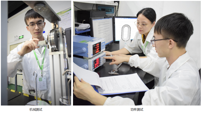 Laboratory technical training
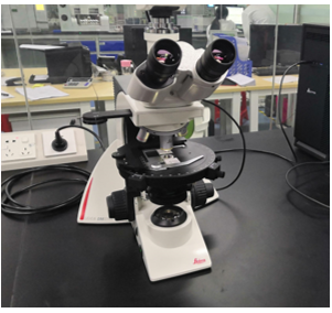 Laboratory Process Consulting
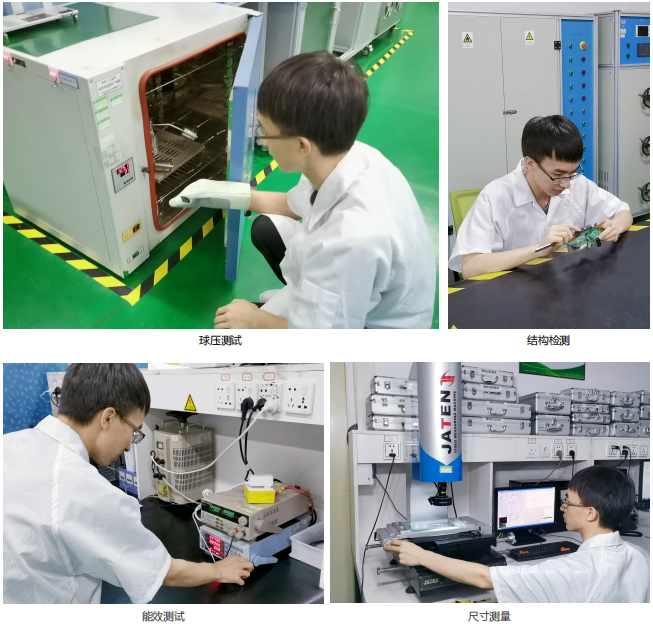 Laboratory decoration construction
Wireless Communication
Electromagnetic compatibility
Automotive Electronics
Automotive Parts Inspection
Electronic appliances
Chemical Testing
Electronic Cigarette Testing
Reliability testing
Battery Testing
Lamp Inspection
Children's toy testing
China Certification
Asia Certification
European Certification
North American Certification
Middle East Certification
Australia Certification
Africa Certification
Other certifications
TRAINING
Wireless Communication
Electromagnetic compatibility
Automotive Electronics
Automotive Parts Inspection
Electronic appliances
Chemical Testing
Electronic Cigarette Testing
Reliability testing
Battery Testing
Lamp Inspection
Children's toy testing
China Certification
Asia Certification
European Certification
North American Certification
Middle East Certification
Australia Certification
Africa Certification
Other certifications
TRAINING
Wireless Communication
Electromagnetic compatibility
Automotive Electronics
Automotive Parts Inspection
Electronic appliances
Chemical Testing
Electronic Cigarette Testing
Reliability testing
Battery Testing
Lamp Inspection
Children's toy testing
China Certification
Asia Certification
European Certification
North American Certification
Middle East Certification
Australia Certification
Africa Certification
Other certifications
TRAINING
Wireless Communication
Electromagnetic compatibility
Automotive Electronics
Automotive Parts Inspection
Electronic appliances
Chemical Testing
Electronic Cigarette Testing
Reliability testing
Battery Testing
Lamp Inspection
Children's toy testing
China Certification
Asia Certification
European Certification
North American Certification
Middle East Certification
Australia Certification
Africa Certification
Other certifications
TRAINING
Wireless Communication
Electromagnetic compatibility
Automotive Electronics
Automotive Parts Inspection
Electronic appliances
Chemical Testing
Electronic Cigarette Testing
Reliability testing
Battery Testing
Lamp Inspection
Children's toy testing
China Certification
Asia Certification
European Certification
North American Certification
Middle East Certification
Australia Certification
Africa Certification
Other certifications
TRAINING
Wireless Communication
Electromagnetic compatibility
Automotive Electronics
Automotive Parts Inspection
Electronic appliances
Chemical Testing
Electronic Cigarette Testing
Reliability testing
Battery Testing
Lamp Inspection
Children's toy testing
China Certification
Asia Certification
European Certification
North American Certification
Middle East Certification
Australia Certification
Africa Certification
Other certifications
TRAINING

EMC testing repeatedly frustrated? Three essential strategies for engineers to learn about fault diagnosis and resolution
Author.
LCS
Source:
Post time:
2026-05-11
In the field of modern electronic product design and manufacturing, the passing or failure of electromagnetic compatibility (EMC) testing directly affects the compliance, stability, and market competitiveness of the product.
EMC testing is a comprehensive examination of these two core capabilities: firstly, measuring the electromagnetic interference intensity radiated or conducted by the product to ensure compliance with standard limits; The second is to evaluate the product's immunity to specific electromagnetic interference to verify its electromagnetic sensitivity.
Faced with the challenges of EMC testing, it is better to master a systematic strategy rather than passively responding after failure. Engineers can build strong EMC fault diagnosis and resolution capabilities from the following three aspects.
The first thing to do when dealing with EMC failures is to understand the testing itself. Many seemingly complex faults may stem from misunderstandings about the testing process, environment, or improper use of instruments. It is crucial to view testing as the first step in the diagnostic process, rather than just determining the results.
Understanding the importance of testing environments:
EMC measurement has extremely high requirements for the site, whether it is an outdoor open field, shielded room, or anechoic chamber, it is all to provide a controllable and highly repetitive testing environment. Understanding the characteristics of different sites and their impact on measurement results can help us analyze whether faults are related to environmental factors. For example, a semi anechoic chamber is mainly used for radiation emission and sensitivity testing, while a shielding chamber is suitable for conduction emission and sensitivity testing.
Familiar with testing equipment and its functions:
EMC measuring equipment can be roughly divided into two categories: those used for measuring electromagnetic interference (such as spectrum analyzers and EMI receivers) and those used for simulating interference sources for sensitivity testing (such as signal sources, power amplifiers, and various coupling/decoupling networks). Especially the spectrum analyzer, it is our 'weapon' for locating interference sources. It can decompose complex time-domain signals into frequency components and clearly display the interference intensity at each frequency point. By identifying the frequency of interference signals, we can often quickly pinpoint the corresponding potential interference sources in the circuit, as frequency characteristics are usually clear and stable in circuit design.
Master the core measurement methods:
There are four main types of EMC testing:
Conducted Emission Test (CE): Evaluating electromagnetic interference conducted through power lines, signal lines, and other pathways.
Radiation emission testing (RE): Evaluating electromagnetic interference emitted through space radiation.
Conducted Sensitivity (Immunity) Test (CS): Evaluating the device's resistance to conducted interference from power lines, signal lines, and other sources.
Radiation Sensitivity (Immunity) Test (RS): Evaluating the device's ability to resist spatial radiation interference.
Understanding the objectives of each test can help us more accurately determine the specific patterns of product failure.
Thorough testing preparation is the foundation of success:
Environmental level requirements: Ensure that the electromagnetic background noise of the testing environment itself is far below the standard limit to avoid interfering with the actual test results.
Isolation of testing table and equipment: Reasonable placement and necessary isolation measures should be taken to prevent unnecessary coupling between the measuring equipment and the device under test (EUT).
Sensitivity discrimination criteria: Clarify the criteria for fault diagnosis, usually provided by the product manufacturer, and quantify the degree of performance degradation through real-time monitoring and observation.
EUT Placement Specification: Strictly follow the standard's provisions for the placement of the tested equipment to ensure the reproducibility of test results.
Through a deep understanding and meticulous execution of the EMC testing process, potential issues in the design can be identified earlier, and even pre testing can be conducted before formal testing, greatly improving diagnostic efficiency.
When a product unfortunately fails EMC testing, the next step is troubleshooting. This requires us to be like doctors, accurately diagnose based on "symptoms" and prescribe effective "prescriptions". EMC faults can be roughly divided into conduction type and radiation type, and their solutions also have their own focuses.
Countermeasures for Conducted Interference:
Conducted interference usually occurs in circuits, and we can solve it through the following approach:
Increase series impedance: Connect high impedance devices (such as ferrite beads) in series along the EMI current path to effectively weaken interference signals.
Provide low impedance bypass: short-circuit EMI current directly to ground or guide it to other circuits through parallel low impedance (such as bypass capacitors) to prevent it from entering sensitive circuits.
Cut off interference path: Use current isolation devices (such as isolation transformers, optocouplers) to block the transmission of EMI current from the source.
Self suppression: By optimizing the design, the interference source itself generates less EMI current.
Specific capacitive and emotional solutions:
1. Capacitive solution: Filter capacitors are commonly used conductive interference suppression devices. The key lies in its correct selection and layout.
Differential mode (line to line) filtering capacitor: used to suppress interference between signal lines or power lines L-N.
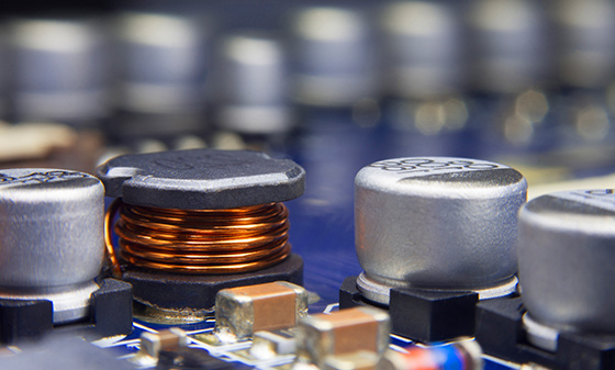
Common mode (line to ground/chassis) filtering capacitor: Small capacitors (10-100nF) are commonly used to short-circuit unwanted high-frequency common mode currents to chassis ground. The key is to reduce parasitic inductance and prioritize the use of leadless components or ultra short leads.
2. Inductive and series loss solution: Inductive devices suppress high-frequency interference through their inductive reactance.
Magnetic core material: Ferrite is a common choice, and its loss characteristics make it have good absorption of interference in a specific frequency range.
Load ferrite cable: effectively suppress high-frequency common mode current on the cable.
Inductance, differential mode, and common mode inductance: Choose the appropriate inductor based on the type of interference.
Grounding choke: specifically designed to suppress common mode current on the ground wire.
When choosing an inductor, it is necessary to consider its saturation current and temperature rise to ensure stable performance under operating current.
Countermeasures for radiation interference:
Radiation interference is a manifestation of energy propagation through space. When solving such problems, we often use shielding techniques. The shielding effect is closely related to the frequency, distance, and electric/magnetic field characteristics of the interference source.
Conductor tape: Copper or aluminum tape is a convenient choice for quickly constructing shielding layers or low impedance connections, especially suitable for temporary repairs or local shielding.
Mesh shielding tape and zipper jacket: These are effective means of providing shielding for cables, especially for installed cables, which can reduce their radiation or improve their immunity.
EMI gasket: When there is radiation leakage in the gaps, interfaces, etc. of the chassis, EMI gasket can provide good conductive connection and shielding effect, and is a commonly used method to solve radiation problems, ESD, EMP and other challenges.
EMI shielding of windows and ventilation panels: For the aperture on the casing (such as display screen windows, heat dissipation holes), conductive grids or conductive glass should be used for shielding to prevent electromagnetic wave leakage or entry.
Conductive coating: provides a conductive shielding layer for plastic shells or improves the shielding effectiveness of existing conductive surfaces.
Conductive foil and conductive cloth: These materials are suitable for various shapes of three-dimensional shielding applications due to their good conductivity and flexibility, especially performing well in the high frequency range.
Troubleshooting is a process of repeated experimentation and verification. By mastering these technologies, we can prescribe targeted solutions and improve the efficiency of problem-solving.
The best EMC solution is not to fix a failed test, but to incorporate EMC considerations from the beginning of product design. The application of new devices and materials can provide stronger electromagnetic "immunity" for products.
Power line filter:
They are installed between the power cord and the equipment, acting like a "cleaner" to filter out parasitic electromagnetic interference in power transmission. It is crucial to choose a suitable filter based on the frequency, voltage, impedance, and load characteristics of the interference source.
Signal isolation transformer:
The core function of this type of transformer (whether pulse type, digital type, or analog isolation type) is to effectively suppress common mode noise without changing the differential mode signal. They provide electrical isolation while maintaining signal integrity by cutting off the ground loop, making them particularly suitable for low noise, low distortion small signal transmission, or in situations with high common mode voltage.
Power isolation transformer and Faraday shield:
Ordinary isolation transformer: capable of cutting off the grounding loop of the main power line in the low-frequency range.
Faraday shielded transformer: Adding a grounding shielding layer (such as aluminum foil or copper foil) between the primary and secondary coils can effectively reduce parasitic capacitance between windings, thereby maintaining good electrical isolation performance in the high frequency range. It is particularly suitable for eliminating ground loops and using in conjunction with power line filters.
transient suppressor :
Such as variable resistors, TVS diodes (TransZorbs), etc., they have nonlinear V-I characteristics and can quickly conduct when the voltage exceeds the set value, clamping the overvoltage at a safe level and protecting sensitive circuits from transient impacts.
Grounding and low impedance connection scheme:
Grounding is the cornerstone of EMC design. Excellent grounding can provide a low impedance path for interference currents, preventing them from radiating or affecting other circuits.
Grounding braided layer or metal strip: Compared to circular wires, flat wires have smaller inductance at the same cross-sectional area and are ideal grounding references.
Printed circuit board (PCB) grounding pad: provides a more direct and low impedance connection point for grounding on the PCB.
Metal cable trunking and its common metal braided layer: As a common ground path between multiple interconnected devices, it can effectively transmit common mode EMI circulating current, especially suitable for large industrial or computer room environments.
Low impedance, elevated metal bottom grounding pad: Building a unified reference grounding plate or grounding network indoors can significantly improve the impact of conducted transient interference and RF fields on the system, and reduce ground potential deviation between different devices.
Temporary grounding plate: In situations where there is a lack of "real" ground, temporary grounding plates can provide effective absorption devices for EMC filters, transient protectors, etc. through large capacitance effects.
Related articles
New articles
Interpretation of LITE technology 9th issue
2026-09-28
Interpretation of LITE Technology 8th Issue
2026-09-24
Media Center
Latest News
Contact Us
National 24-hour service hotline
400-116-2629
Group Headquarters
E-mail: webmaster@lcs-cert.com
Address: Shenzhen City, Baoan District, Shajing Street, Nga side of the school of Wei Juji Industrial Park, Building A 1 ~ 2 floor, Building C 3 floor


 WeChat Inquiry


 Reservation


Contact Us
National 24-hour service hotline
Address:Juji Industrial Park, Xueziwei, Ngabian, Shajing Street, Baoan District, Shenzhen Building A 1~2F, Building C 3F

WeChat public number
Share industry dry goods

WeChat consultation
Please note consulting services

Follow Jitterbug

Mobile website
di complaint mailbox: customer.complaint@lcs-cert.com complaint telephone tel: 18126445450 certificate report verification of authenticity mailbox: verification@lcs-cert.com